Small-volume low-rigidity airbag spring
A low-stiffness, small-volume technology, used in springs, springs/shock absorbers, gas shock absorbers, etc., can solve the problem of low utilization of airbag effective volume, achieve small occupied space, constant natural frequency, and improve utilization. Effect
- Summary
- Abstract
- Description
- Claims
- Application Information
AI Technical Summary
Problems solved by technology
Method used
Image
Examples
Embodiment 1
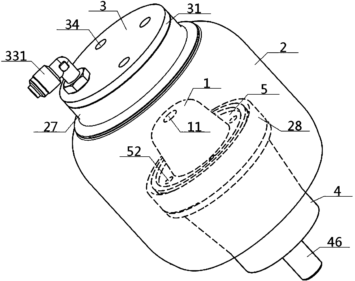
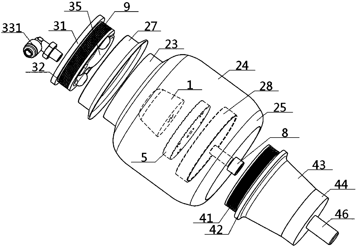
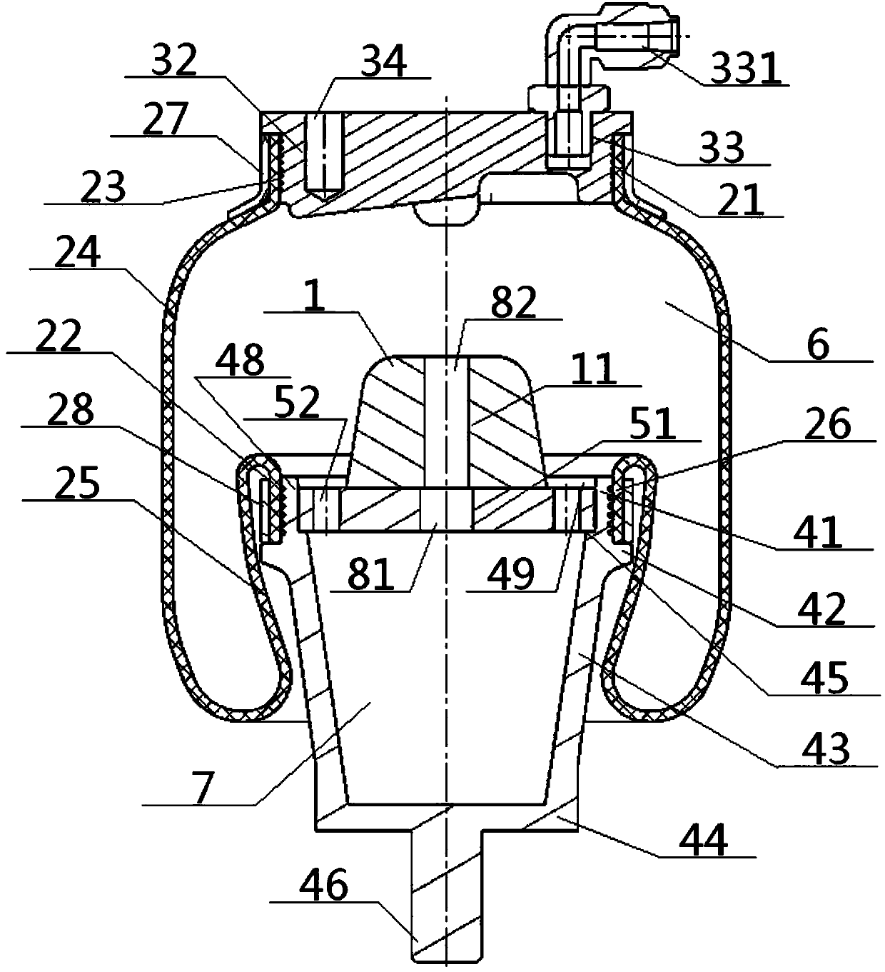
[0053] see Figure 1 to Figure 4 , a small-volume low-rigidity airbag spring, comprising an outer capsule body 2, an upper cover plate 3, a piston 4 and a buffer block 1, the top port 21 and the bottom port 22 of the outer capsule body 2 are respectively connected to the upper cover plate 3, the piston 4 are connected, and a buffer block 1 is provided inside the outer capsule body 2; the outer capsule body 2 includes a top bag portion 23, a side bag portion 24, a concave bag portion 25 and a bottom bag portion 26, and the top bag portion 23 The middle part is the top port 21, the inner wall of the top port 21 is connected with the outer wall of the upper cover plate 3 embedded therein, the bottom end of the top bag part 23 is connected with the top end of the side bag part 24, and the bottom of the side bag part 24 end is connected with the bottom end of the pocket part 25, and the top end of the pocket part 25 is connected with the top end of the bottom pocket part 26, and th...
Embodiment 2
[0055] Basic content is the same as embodiment 1, the difference is:
[0056] The middle part of the flange tray 5 is provided with a through hole 51 in the tray, and the middle part of the buffer block 1 is provided with a shaft through hole 11. The through hole 51 in the tray is connected with the shaft through hole 11 through a long connector 8, and the long connector 8 The bottom of the long connector 8 is located inside the through hole 51 in the tray, and the top of the long connector 8 is located inside the shaft through hole 11 . Preferably, the long connecting piece 8 is a hexagon socket head bolt, comprising interconnected bolt heads 81 and bolt posts 82, the diameter of the bolt heads 81 is greater than the diameter of the bolt posts 82, and the bottom surface of the bolt heads 81 is flush with the bottom surface of the through hole 51 in the tray , the intersection of the bolt head 81 and the bolt column 82 coincides with the intersection of the through hole 51 in ...
Embodiment 3
[0058] Basic content is the same as embodiment 1, the difference is:
[0059] Preferably, the buffer block 1 is a frustum of cone with a narrow top and a wide bottom. Preferably, the position connected to the inner wall of the top port 21 on the upper cover plate 3 and the position connected to the inner wall of the bottom port 22 on the outer wall of the piston 4 are all provided with an annular groove 9, and the effect of the annular groove 9 is to enhance the sealing performance on the one hand. On the other hand, it is to increase the holding (friction) force to prevent the separation of the airbag from the upper cover plate 3 and the piston 4; the upper ring of the outer wall of the top port 21 connected with the upper cover plate 3 is provided with an upper hoop 27 , The bottom port 22 is provided with a lower hoop 28 on the outer wall upper ring of the part connected to the piston 4 . Preferably, the number of tray-side through holes 52 is four, and they are uniformly ...
PUM
 Abstract
Description
Claims
Application Information
 - R&D
- Intellectual Property
- Life Sciences
- Materials
- Tech Scout
- Unparalleled Data Quality
- Higher Quality Content
- 60% Fewer Hallucinations
Browse by: Latest US Patents, China's latest patents, Technical Efficacy Thesaurus, Application Domain, Technology Topic, Popular Technical Reports.
© 2025 PatSnap. All rights reserved.Legal|Privacy policy|Modern Slavery Act Transparency Statement|Sitemap|About US| Contact US: help@patsnap.com


