Multi-angle vibration control swinger

A sweeping instrument and multi-angle technology, applied in the field of sweeping instruments, can solve the problems of poor environmental adaptability, great impact on instrument accuracy, and large cost, and achieve the effects of small mechanical burden and mechanical loss, improved battery life, and reduced requirements

Inactive Publication Date: 2018-04-13
SUZHOU YIDI ELECTRONICS TECH
View PDF0 Cites 0 Cited by
  • Summary
  • Abstract
  • Description
  • Claims
  • Application Information

AI Technical Summary

Problems solved by technology

At present, the commonly used leveling methods are mainly manual leveling and instrument self-leveling. Artificial leveling has strong adaptability to the environment, but manual leveling has a greater impact on the accuracy of the instrument; Placing the instrument on a relatively flat position has extremely poor adaptability to the environment. In actual use, if the reference plane needs to be tilted at a certain angle, the current leveling instrument either needs to manually spend a lot of time to re-adjust the angle, or It is not possible to adjust large angles at all.
Therefore, the current instruments are still unable to meet the fast and convenient requirements of engineering construction operations and the requirements of some special occasions.
In addition, the sweeper needs to perform violent mechanical movements during sweeping, which results in heavy wear and vibration.

Method used


Image

  • Multi-angle vibration control swinger
  • Multi-angle vibration control swinger
  • Multi-angle vibration control swinger

Examples


Embodiment

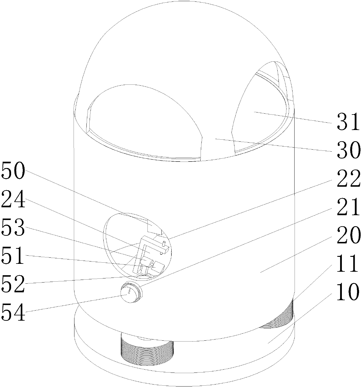
[0025] refer to Figure 1 to Figure 3 As shown, the present invention discloses a multi-angle choke sweeper, comprising a base 10 , a casing 20 and a casing cover 30 .

[0026] The above-mentioned base 10 is provided with a leveling unit 11 . The above-mentioned housing 20 is provided on the safety unit 11 . The leveling unit 11 can level the casing 20 .

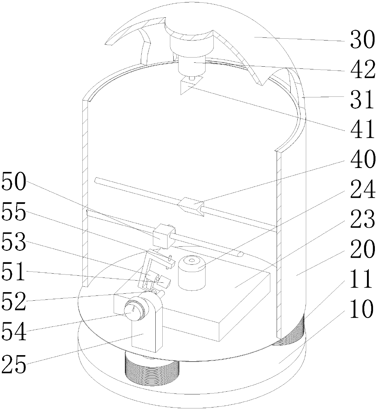
[0027] The above-mentioned case cover 30 is provided on the case 20 . The shell cover 30 is in the shape of a spherical shell, and a horizontal window 31 for the reference light surface to exit is opened along the circumferential direction thereof.

[0028] The bottom of the casing 20 is provided with a laser transmitter 23 . The laser emitter 23 is connected with a laser emitting head 24 arranged in a vertical direction. A beam splitter 40 is provided on the optical path of the laser exit head 24 , and the beam splitter 40 is fixed on the casing 20 through a connecting rod. The beam splitter 40 may be a triangular pri...


PUM


Abstract

The invention discloses a multi-angle choke leveling instrument, which comprises a casing, a laser emitter, a beam splitter, a horizontal reflector and a variable angle reflector, the laser emitter is arranged at the bottom of the casing; the horizontal reflector is arranged At the shaft end of the horizontal mirror rotation motor inverted on the casing, the angle-changing mirror is arranged on the shaft end of the rotation motor of the angle-changing mirror, and the rotation motor of the angle-changing mirror is arranged on the side wall of the casing. On the rotating shaft, a light-emitting head is arranged on the rotating shaft, the central axis of the light-emitting head, the central axis of the rotating motor of the angle-changing mirror, and the central axis of the rotating shaft are orthogonal to each other, and the intersection point is located on the mirror surface of the angle-changing mirror Above, the light output head is connected with a light receiver arranged on the housing, and the horizontal reflector and the light receiver are respectively located on the two optical paths of the beam splitter. It can quickly adjust the reference plane at multiple angles, has strong versatility, less mechanical wear and vibration, greatly improves work efficiency and reduces personnel workload.

Description

technical field [0001] The invention relates to a sweeper, in particular to a multi-angle choke-vibration sweeper. Background technique [0002] The leveler is an instrument commonly used to determine the horizontal or vertical plane. The leveler should be leveled before working. At present, the commonly used methods of leveling are mainly manual leveling and instrument self leveling. Artificial leveling has strong adaptability to the environment, but artificial leveling has a greater impact on the accuracy of the instrument. The instrument is placed in a relatively flat position, which has poor adaptability to the environment. In actual use, if the reference plane needs to be inclined at a certain angle, the current leveling instrument either needs to spend a lot of time manually to adjust the angle again, or It is impossible to adjust the large angle at all. Therefore, the current instruments cannot meet the requirements of fast and convenient construction operation and ...

Claims


Application Information

Patent Timeline
Patent Type & Authority Applications(China)
IPC IPC(8): G01C15/00
CPCG01C15/004
Inventor 薛启昊
Owner SUZHOU YIDI ELECTRONICS TECH
Why Eureka
Try Eureka