Core adjusting bracket

A core-adjusting and hole-adjusting technology, applied in the field of brackets, can solve the problems of inability to align end faces, cumbersome and complicated work of end face alignment, time-consuming and labor-intensive, etc., and achieves the effect of concrete structure and convenient industrialized processing and production.

Pending Publication Date: 2018-04-13
NANJING JILONG OPTICAL COMM
View PDF0 Cites 6 Cited by
  • Summary
  • Abstract
  • Description
  • Claims
  • Application Information

AI Technical Summary

Problems solved by technology

[0002] The alignment bracket is an important part of the optical fiber fusion splicer. Its function is to limit the position of the two optical fibers before the optical fiber welding, to ensure that the end faces of the two optical fibers are aligned with each other, and to ensure the accuracy of welding. Most of the existing alignment bracket

Method used


Image

  • Core adjusting bracket
  • Core adjusting bracket
  • Core adjusting bracket

Examples


Embodiment Construction

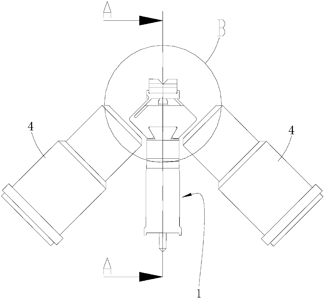
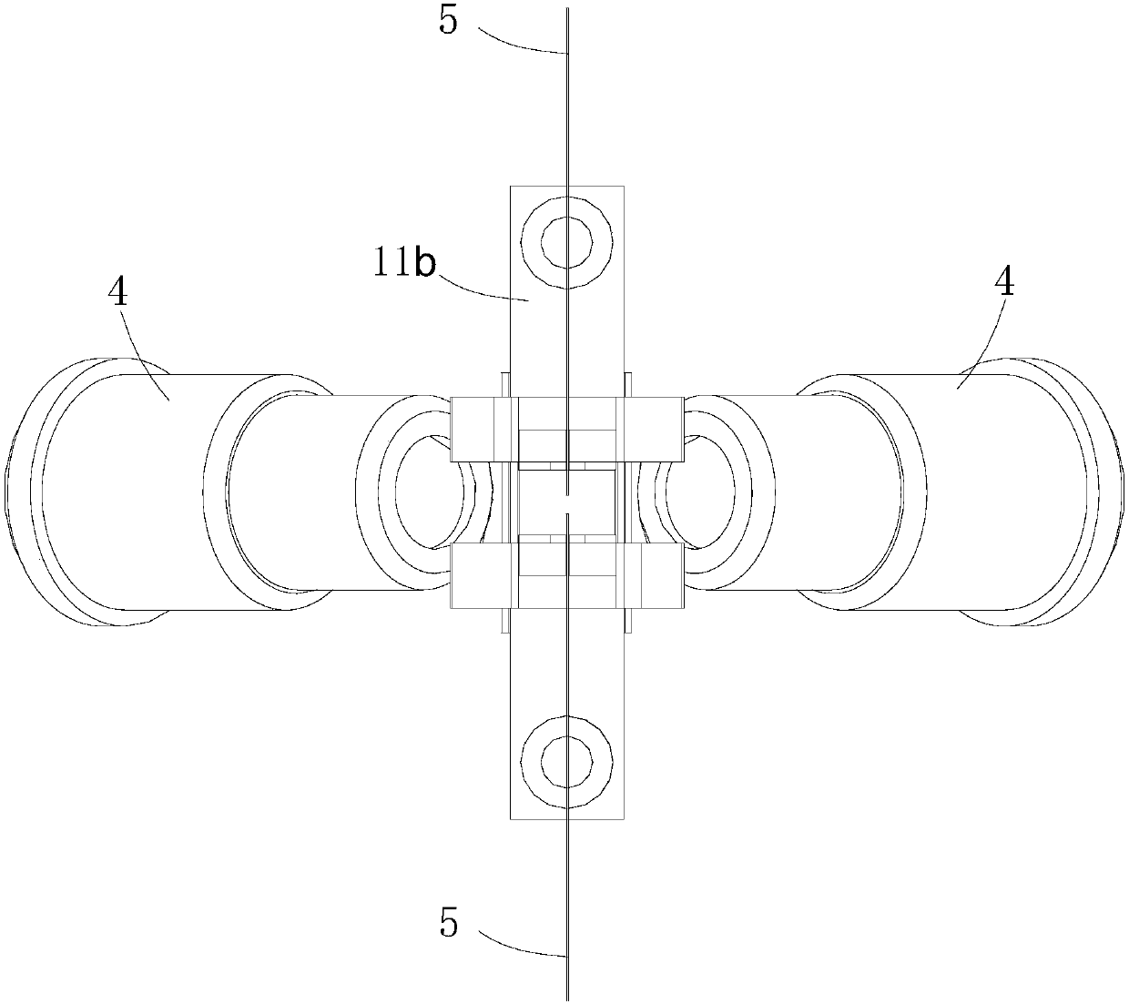
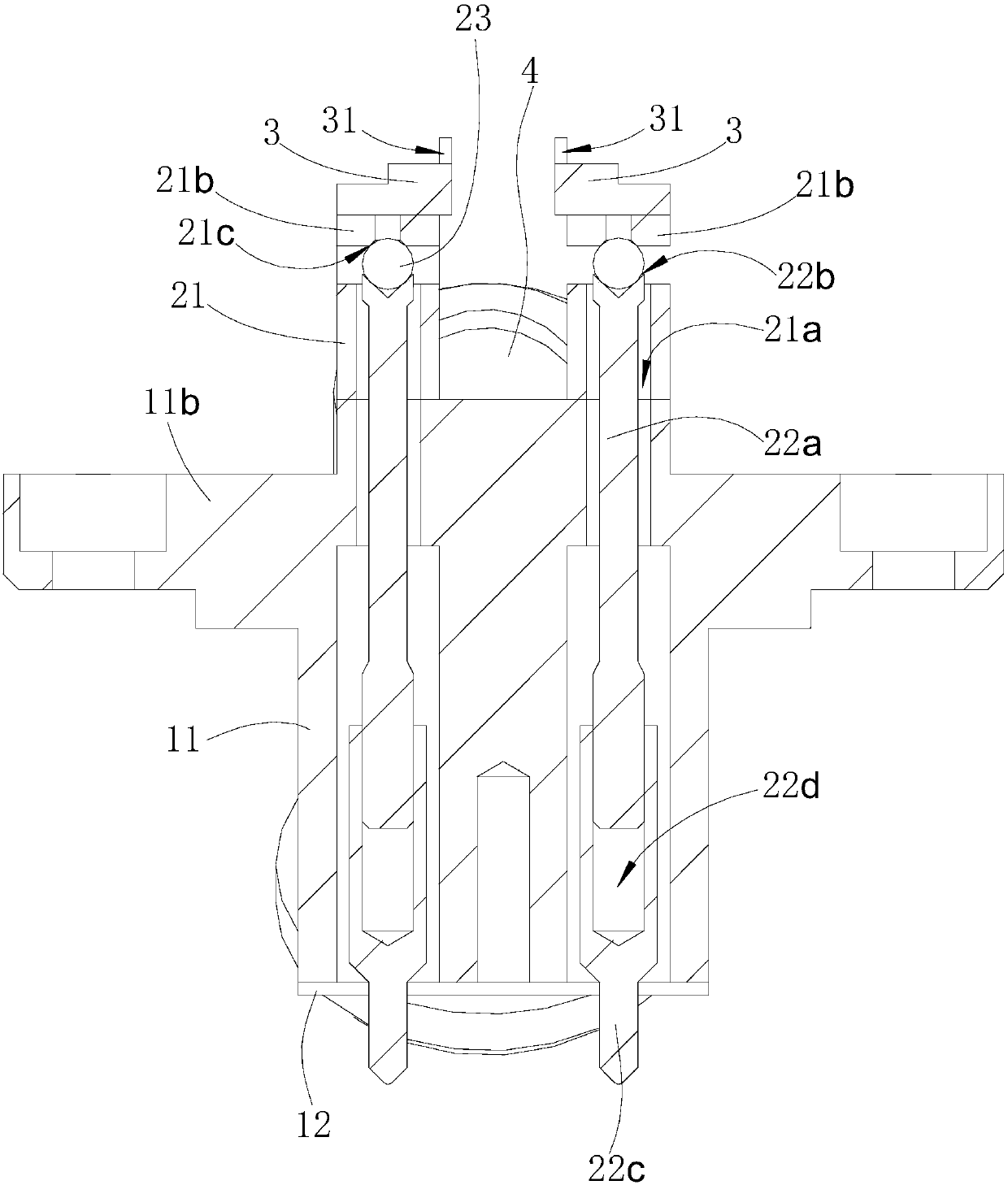
[0019] Such as Figures 1 to 5 as shown ( Figure 5 The section direction of image 3 same section direction)

[0020] The alignment bracket includes a housing 1 , two sets of adjustment components and two sets of optical fiber positioning blocks 3 .

[0021] The housing 1 includes a housing body 11 and an installation baffle 12. The housing body 11 is provided with two first adjustment stage holes 11a that pass through its upper and lower end surfaces. The installation baffle 12 corresponds to the position of the first adjustment stage hole 11a of the housing body 11. There are two second adjustment stage holes 12a, and the installation baffle 12 is at the lower part of the shell body 11 through fastening screws (not shown in the figure), and the first adjustment stage hole 11a of the shell body 11 corresponds to the first adjustment stage 12 of the installation baffle 12 The two adjustment stage holes 12a together form the adjustment hole of the housing 1, and the outer w...


PUM


Abstract

The invention provides an alignment bracket; it includes a housing, at least one set of adjustment assemblies and at least one optical fiber positioning block, and at least one adjustment hole is opened in the housing; the elastic member of the adjustment assembly is opened at the position of the adjustment hole corresponding to the housing There is a through hole, an independent swing rod extends from the surface of the elastic member to the upper side of the through hole, the transmission rod runs through the through hole of the elastic member and the corresponding adjustment hole of the housing, the lower end of the transmission rod protrudes from the lower side of the adjustment hole, and the steel ball is placed on the Between the upper end of the transmission rod and the end of the swing rod, the optical fiber positioning block is fixed on the corresponding upper end of the swing rod, and the upper end surface of the optical fiber positioning block is provided with a limiting groove for placing the optical fiber. According to the relative position of the two optical fiber end faces placed in the two optical fiber positioning blocks, the external mechanism can be controlled to act on the lower end of the transmission rod, so that the transmission rod drives the upper steel ball to shift, so that the swing rod of the elastic member is relative to the body of the elastic member. By swinging, the end faces of the two optical fibers placed in the limit groove can be aligned and meet the fusion splicing requirements.

Description

technical field [0001] The invention relates to a bracket, in particular to a core-adjusting bracket used in an optical fiber fusion splicer. Background technique [0002] The alignment bracket is an important part of the optical fiber fusion splicer. Its function is to limit the position of the two optical fibers before the optical fiber welding, to ensure that the end faces of the two optical fibers are aligned with each other, and to ensure the accuracy of welding. Most of the existing alignment brackets are Fixed alignment bracket, the alignment bracket cannot be moved, but the optical fiber is placed behind the fiber positioning block, the problem of misalignment of the end face is prone to occur, and manual adjustment is required. Because the optical fiber is thin, the end face alignment is cumbersome, time-consuming and laborious. Contents of the invention [0003] The technical problem to be solved by the present invention is to provide a core-adjusting bracket cap...

Claims


Application Information

Patent Timeline
IPC IPC(8): G02B6/255
CPCG02B6/2555
Inventor 倪庆亮杨炳坤高远
Owner NANJING JILONG OPTICAL COMM
Why Eureka
Try Eureka