
Laser driven microwave pulse emitting device

A pulse emission and laser-driven technology, applied in the field of microwave radiation, can solve the problems of transient output power limitation, high maintenance cost, complex structure, etc., and achieve the effect of easy miniaturization, convenient maintenance, and simple device structure

Pending Publication Date: 2018-04-13
LASER FUSION RES CENT CHINA ACAD OF ENG PHYSICS
View PDF6 Cites 3 Cited by
  • Summary
  • Abstract
  • Description
  • Claims
  • Application Information

AI Technical Summary

Problems solved by technology

There are some disadvantages in the traditional pulse discharge method. Firstly, a relatively large charging and discharging device such as a large capacitor bank is required to generate a large current output, resulting in a larger system volume, a more complicated structure, and higher maintenance costs.
Secondly, the traditional pulse discharge method has certain restrictions on the realization of transient high-power microwave pulse radiation. Generally, the shorter the pulse width of the driving current, the higher the transient power converted into microwave radiation.
The current pulse width generated by pulse charging and discharging is usually on the order of nanoseconds. Due to the bottleneck of electronic technology, it is difficult to achieve the pulse width of picoseconds and femtoseconds, so its transient output power is limited to a certain extent.

Method used


Image

  • Laser driven microwave pulse emitting device
  • Laser driven microwave pulse emitting device

Examples


Embodiment Construction

[0017] The present invention will be described in detail below with reference to the accompanying drawings and examples.

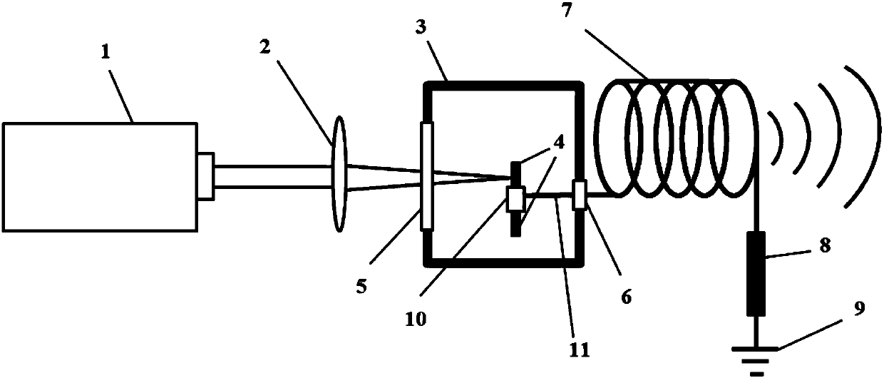
[0018] This embodiment provides a laser-driven microwave pulse emission device, see the attached figure 1 , including: pulse laser 1, focusing lens 2, vacuum cavity 3, metal sheet 4, glass window 5, vacuum electrical connection plug 6, metal coil 7, matching resistor 8, rotating shaft 10 and wire 11;

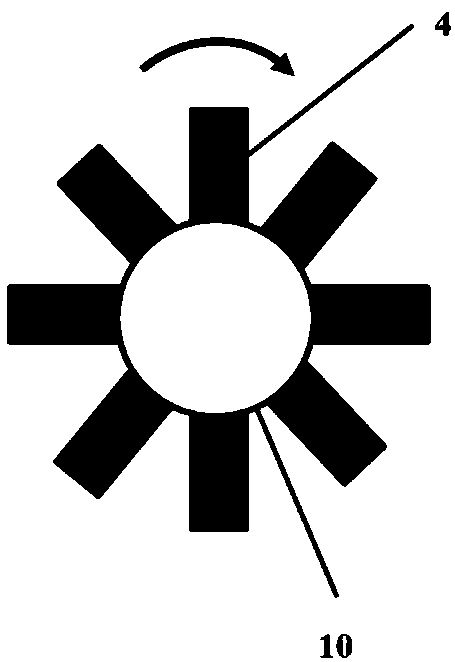
[0019] More than two metal sheets 4 are fixed on the rotating shaft 10 along the circumferential direction; the rotating shaft 10 is fixed in the vacuum chamber 3, and the rotating shaft 10 can rotate around its axis under the action of the motor; the rotating shaft 10 is fixed in the vacuum chamber through the wire 11 One end of the vacuum electrical connection plug 6 on the side of the body 3 is electrically connected, and the other end of the vacuum electrical connection plug 6 is electrically connected to one end of the metal coil 7 located outside the v...


PUM


Abstract

The invention discloses a laser driven microwave pulse emitting device, belonging to the technical field of microwave radiation. The laser driven microwave pulse emitting device comprises a pulsed laser, a focusing lens, a vacuum chamber, a metal sheet, a glass window, a metal coil and a matching resistor; wherein the metal sheet is installed in the vacuum chamber, and the metal sheet is electrically connected with one end of the metal coil outside the vacuum chamber; the other end of the metal coil is connected to the earth through the matching resistor; the glass window is fixed on the sideof the vacuum chamber to make the vacuum chamber in a sealed vacuum state; both the pulsed laser and the focusing lens are mounted on the side of the glass window where the vacuum chamber is located,and the laser emitted by the pulsed laser is located on the same optical axis with the focusing lens; and the laser emitted by the pulsed laser is focused through the focusing lens and enters the vacuum chamber after passing through the glass window, and then falls perpendicularly to the surface of the sheet metal. The laser driven microwave pulse emitting device can convert laser energy into microwave pulse energy for emitting, and has the characteristics of simple realization and flexible adjustment.

Description

technical field [0001] The invention belongs to the technical field of microwave radiation, and in particular relates to a laser-driven microwave pulse emitting device. Background technique [0002] Microwave pulse is a kind of microwave radiation used in the fields of industrial manufacturing, scientific research, national defense and military affairs. Usually, people use pulse discharge to drive the transmitting antenna to generate microwave pulse radiation. There are some disadvantages in the traditional pulse discharge method. Firstly, a relatively large charging and discharging device such as a large capacitor bank is required to generate a large current output, resulting in a larger system size, a more complicated structure, and higher maintenance costs. Secondly, the traditional pulse discharge method has certain restrictions on the realization of transient high-power microwave pulse radiation. Generally, the shorter the pulse width of the driving current, the higher ...

Claims


Application Information

Patent Timeline
Patent Type & Authority Applications(China)
IPC IPC(8): H01S1/02
CPCH01S1/02
Inventor 易涛王传珂
Owner LASER FUSION RES CENT CHINA ACAD OF ENG PHYSICS
Learn More