
Unpowered ore separator

A technology of ore separator and power, applied in the field of mining machinery and equipment, can solve the problems of high processing and manufacturing costs, uneven ore separation, high energy consumption, etc., and achieve the effects of low processing and production costs, uniform ore separation, and simple manufacturing process

Pending Publication Date: 2018-04-17
KUNMING UNIV OF SCI & TECH
View PDF0 Cites 1 Cited by
  • Summary
  • Abstract
  • Description
  • Claims
  • Application Information

AI Technical Summary

Problems solved by technology

[0006] The technical problem to be solved by the present invention is to overcome the deficiencies of the prior art, such as uneven ore separation, high processing and manufacturing costs, non-wear resistance, high energy consumption, etc., to provide a non-powered ore separation device

Method used


Image

  • Unpowered ore separator
  • Unpowered ore separator

Examples


Embodiment 1

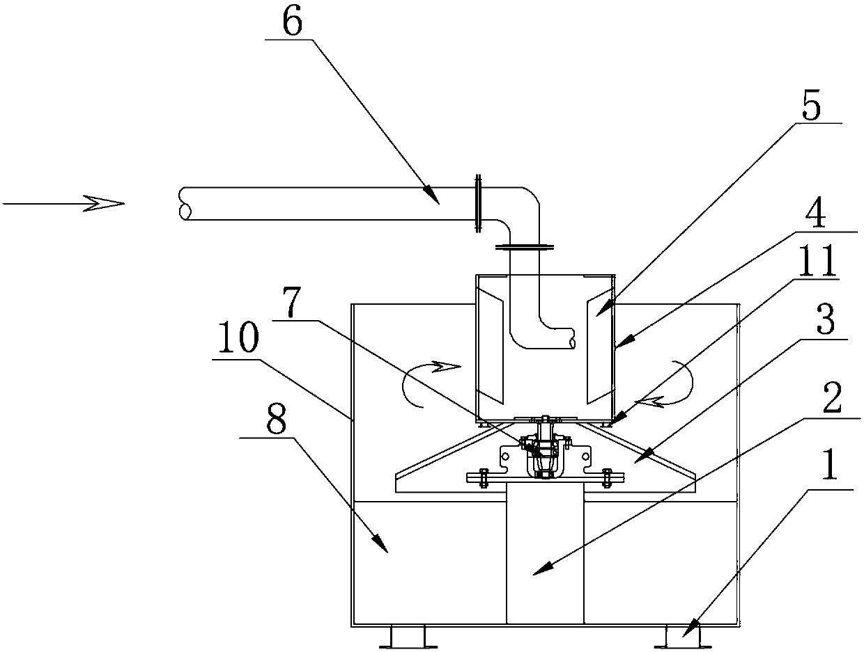
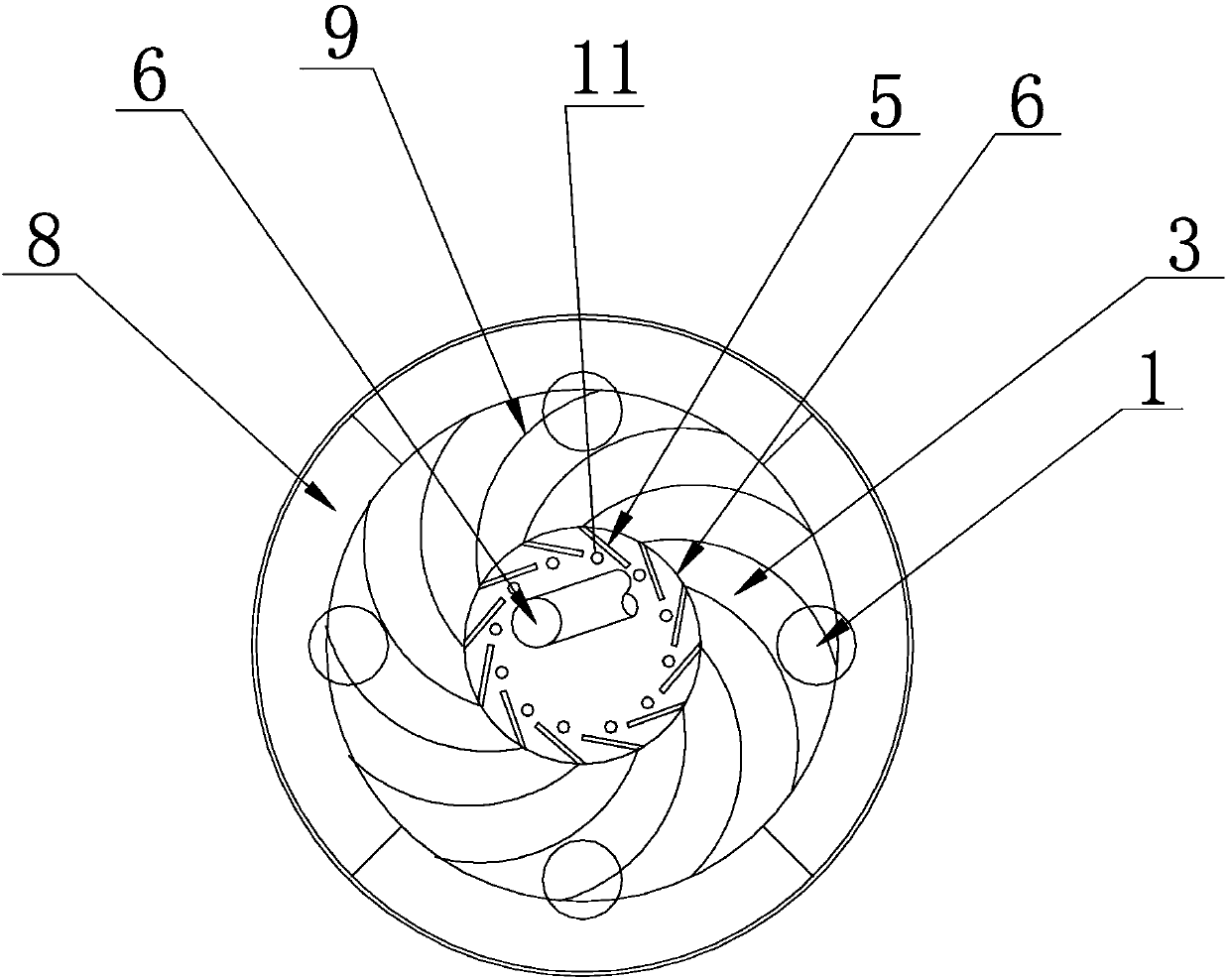
[0040] The non-powered ore separator described in this embodiment is used for gravity feeding equipment, see figure 1 , figure 2 , a structural schematic diagram of a non-powered ore separator, a top view structural diagram of a non-powered ore separator, a non-powered ore separator, including an ore separation pipe 1, a transmission device base 2, and a conical ore separator 3 , power bucket 4, blade 5, pulp pipe 6, transmission device 7, ore-connecting tank 8, ore-splitting bar 9, body 10, artesian outlet 11, the inside of the body 10 is provided with a transmission device base 2, and the transmission device The upper part of the base 2 is provided with a transmission device 7, the upper part of the transmission device 7 is provided with a power bucket 4, the inner wall of the power bucket 4 is provided with blades 5, the top of the power bucket 4 is provided with a slurry pipe 6, and the power bucket 4 The bottom is provided with a cone-shaped ore separator 3, which is fi...

Embodiment 2

[0053] The unpowered ore separator described in this embodiment is used for flotation equipment feeding, see figure 1 , figure 2 , a structural schematic diagram of a non-powered ore separator, a top view structural diagram of a non-powered ore separator, including an ore separation pipe 1, a transmission base 2, a conical separator 3, a power barrel 4, blades 5, Ore slurry pipe 6, transmission device 7, ore-connecting tank 8, ore-distributing bar 9, body 10, artesian outlet 11.

[0054] Compared with Embodiment 1, for the description of the structure of the non-powered ore separator in this embodiment, the similarities will not be repeated.

[0055] The use occasions 4-5 described below are supplementary descriptions of the second embodiment.

[0056] Use occasion 4: 3-stage parallel lead concentration flotation machine feeding ore

[0057] Technical index requirements: the distribution volume of a single mine separator is 1.8t / h, and the concentration of ore quality is 2...


PUM


Abstract

The invention discloses an unpowered ore separator for uniformly separating ores. The unpowered ore separator comprises ore separation pipes, a transmission device base, a cone-shaped ore separator, apower bucket, blades, an ore pulp pipe, a transmission device, an ore receiving groove, ore separation strips, a machine body and an automatic flow hole, wherein the transmission device base is arranged in the machine body, the transmission device is arranged on the transmission device base, the power bucket is arranged on the transmission device, the blades are arranged on the inner wall of thepower bucket, the ore pulp pipe is arranged at the top of the power bucket, the cone-shaped ore separator is arranged at the bottom of the power bucket and is fixedly connected with the transmission device, the ore separation strips are arranged in the cone-shaped ore separator, the ore receiving groove is formed in the lower part of the cone-shaped ore separator, the ore separation pipes are arranged at the bottom of the ore receiving groove, and the automatic flow hole is formed in the bottom of the power bucket. The unpowered ore separator simultaneously has stirring and ore separation effects and can be used for uniformly separating ores, does not require power consumption and power input, and is low in machining production cost, light in weight and wear-resistant, and the production and investment costs can be greatly lowered; and the unpowered ore separator is simple in structure, easy to manufacture, convenient to mount and strong in applicability.

Description

technical field [0001] The invention relates to a kind of ore dressing equipment, in particular to a kind of ore separating equipment, specifically a non-powered ore separating device, which is used for evenly separating ore (ore pulp distribution), and belongs to the technical field of mining machinery and equipment. Background technique [0002] In the mineral processing operation process, it is often necessary to transport the ore pulp to the separation equipment, and then distribute it to two or more simultaneous parallel operation of the mineral processing equipment in the next operation. Whether ore separation (i.e. pulp distribution) is uniform and whether the feeding amount is stable or not will have a great impact on the operation stability of subsequent equipment and process flow. For example, when feeding coal slurry to two coal slime grading screens, due to the uneven distribution of slurry in the separation equipment, the concentration of the slurry fed to one o...

Claims


Application Information

Patent Timeline
IPC IPC(8): B03B11/00
CPCB03B11/00
Inventor 叶国华郎剑涛郎启斌项鹏志路璐童雄胡艺博
Owner KUNMING UNIV OF SCI & TECH
Learn More