Supercharge Your Innovation With Domain-Expert AI Agents!

Rotational joint mechanical arm gravity compensation mechanism

A technology of rotating joints and gravity compensation, applied in the directions of manipulators, manufacturing tools, joints, etc., can solve the problems of inability to achieve accurate sine law changes, the compensation range is not very large, and the control algorithm is complex, so as to solve the problem of limited rotation angle range and avoidance. Structural interference, smooth and reliable motion

Active Publication Date: 2018-04-17
YANSHAN UNIV
View PDF9 Cites 10 Cited by
  • Summary
  • Abstract
  • Description
  • Claims
  • Application Information

AI Technical Summary

Problems solved by technology

Theoretically speaking, this method can realize the complete gravity compensation of the mechanical arm, but the control algorithm is quite complicated; the second is to use the energy storage device for passive torque compensation, and drive the gravity compensation device to move through the mechanical arm joints, and the output of the gravity compensation device is opposite to the gravity moment, passive gravity compensation only needs to design the gravity compensation mechanism, and does not consume excess energy
[0004] Existing passive gravity compensation mechanisms, such as: suspension spring structure, parallel four-bar mechanism and tension spring structure, etc., cannot satisfy the nonlinear change of gravity moment, so they can only perform approximate compensation; cam tension spring structure, compensation The precision is high, but the point and line contact of the cam mechanism has relatively large wear and tear, and the cam stroke is relatively small, and the compensation range is not very large; there is a patent with the publication number CN 104245250A, which discloses the gravity of a pair of non-circular gears and tension springs. Compensation mechanism, and gravity compensation for the manipulator with high degree of freedom, the gravity moment of the manipulator whose axis of rotation joint is parallel to the ground changes according to the sinusoidal law, and the meshing of a pair of non-circular gears cannot realize the function of the precise sinusoidal law change, so Approximate Gravity Compensation

Method used


Image

  • Rotational joint mechanical arm gravity compensation mechanism
  • Rotational joint mechanical arm gravity compensation mechanism
  • Rotational joint mechanical arm gravity compensation mechanism

Examples


Embodiment 1

[0027] Example 1: Gravity Compensation for the Parallel Four 2R Manipulator

[0028] Such as Figure 6A As shown, the 2R mechanical arm includes: 33 large arms, 32 small arms, 29 links A, 30 links B, and 31 links C of the four-bar mechanism.

[0029] One end of the robot arm 33 can rotate around a rotation axis L, and the rotation axis L is parallel to the ground F. As shown in FIG. One end of the small arm 32 is disposed on the front end of the large arm 33 , and the small arm 32 can rotate around the rotation axis U, and the rotation axis U is parallel to the rotation axis L. As shown in FIG. The connecting rod A and connecting rod C of the four-bar mechanism are always parallel to the small arm 32 , and the connecting rod B is always parallel to the big arm 33 .

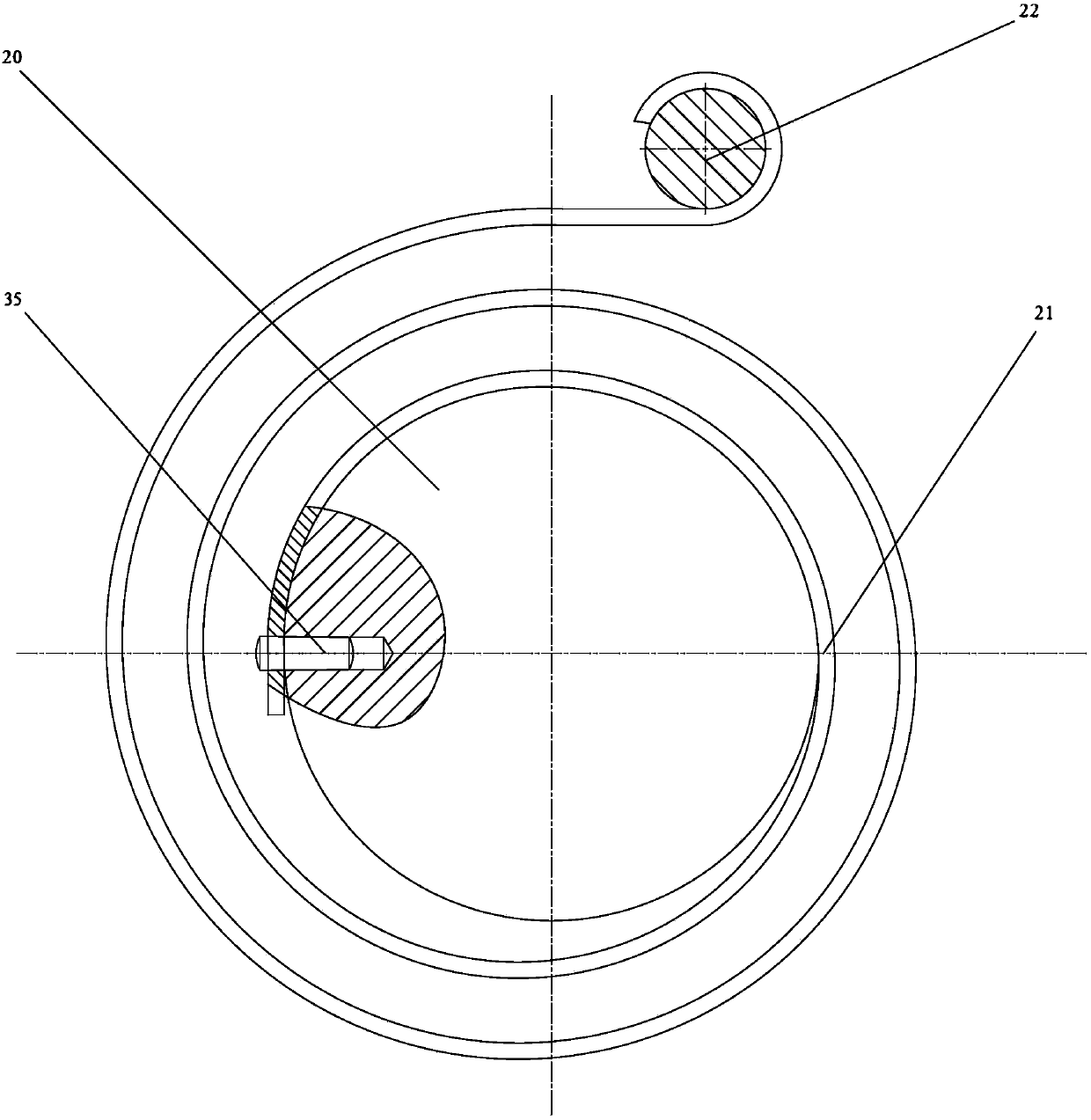
[0030] Such as Figure 6B As shown, the initial positions of the boom 33 and the small arm 32 are shown by the solid line, and the dotted line is the position after the movement. The plane scroll spring 21 in t...


PUM


Abstract

The invention discloses a rotational joint mechanical arm gravity compensation mechanism, which comprises a rack, a non-circular gear planetary gear train and a plane volute spiral spring. The rack comprises a plane volute spiral spring outer end fixing rod; the non-circular gear planetary gear train comprises a tie bar, a planetary shaft, a rotary shaft, a fixed circular sun wheel, a planetary circular gear, a non-circular sun wheel and a planetary non-circular gear; the circular sun wheel is fixed onto the rack through a flange; the tie bar is connected with the planetary shaft in a sleevingway; two ends of the planetary shaft are connected with the planetary circular gear and the planetary non-circular gear; the planetary circular gear is meshed with the fixed circular sun wheel; the planetary non-circular gear is meshed with the rotary non-circular sun wheel; the rotary shaft rotates along with the non-circular sun wheel; the inner end of the plane volute spiral spring is connected with the rotary shaft through a pin; the outer end of the plane volute spiral spring is connected with a fixing rod of the rack; the tie bar is an input component; and the non-circular gear planetary gear train enables the rotary shaft to output a certain amount of turning angles, and the plane volute spiral spring is further torqued, so that an anti-balance moment is produced. The rotational joint mechanical arm gravity compensation mechanism provided by the invention is simple in structure, stable and reliable to move, high in gravity compensation precision, and applicable to a continuousrotating mechanism.

Description

technical field [0001] The invention relates to the fields of industrial robots, rehabilitation medical robots and service robots, and in particular to a gravity compensation mechanism. Background technique [0002] In the design of the robot system, for the mechanical arm whose joint axis is parallel to the ground, due to the gravity of the mechanical arm itself, additional torque will be generated at the joint, which not only reduces the dynamic characteristics of the mechanical arm to a certain extent, but also reduces the dynamic characteristics of the mechanical arm during braking. When the system fails, there is no other self-locking device, and the mechanical arm will fall under the action of gravity, seriously threatening the safety of the operator or other devices. [0003] At present, there are two existing gravity compensation methods: one is to use control means to drive the motor for active torque compensation, which requires real-time measurement of the angle o...

Claims


Application Information

Patent Timeline
IPC IPC(8): B25J17/00B25J19/00
CPCB25J17/00B25J19/0016
Inventor 杨彦东李新亮
Owner YANSHAN UNIV
Features
  • R&D
  • Intellectual Property
  • Life Sciences
  • Materials
  • Tech Scout
  • Unparalleled Data Quality
  • Higher Quality Content
  • 60% Fewer Hallucinations
Learn More