Weight-loss machine

The technology of a weightless machine and a support rod, which is applied in the direction of a lifting device and the like, can solve the problems of ineffective recovery and utilization of gravitational potential energy, laborious, inconvenient force application, etc., and achieve the effects of simple structure, convenient force application, and simple and convenient operation.

Pending Publication Date: 2018-04-17
曾德高
View PDF6 Cites 0 Cited by
  • Summary
  • Abstract
  • Description
  • Claims
  • Application Information

AI Technical Summary

Problems solved by technology

[0003] The existing lifting equipment has certain defects in the process of use. During the lifting process, the lifting force is used from the bottom to the top. It is inconvenient to apply force during the lifting process, and generally requires a force equal to that of the heavy object. It is labor-intensive; in order to save labor, most of them are implemented by moving pulleys, and combined with fixed pulleys to achieve direction-changing lifting, but the gravitational potential energy of the heavy object is not effectively recycled during the process of falling.

Method used


Image

  • Weight-loss machine
  • Weight-loss machine
  • Weight-loss machine

Examples


Embodiment 1

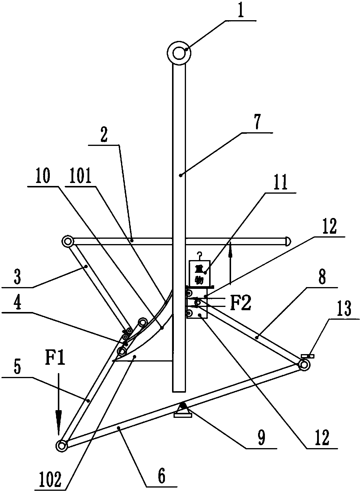
[0023] In the weightless machine of the present invention, "weightlessness" is not the state of weightlessness in physics, but the weight is lifted with a force much smaller than the weight of the lifted object, so that it is equivalent to the weightless state of the heavy object on the surface, so it is named the weightless machine .

[0024] see Figure 1-3 , the present invention provides the following technical solutions:

[0025] Such as figure 1 , figure 2 As shown, the weightless machine of this embodiment includes a fixed seat 1, a tie rod 2, a first movable support rod 3, a movable assembly 4, a second movable support rod 5, a balance bar 6, a movable plate 7, and a third movable support rod 8. Support base 9, weight 11; the movable plate 7 is installed under the fixed base 1 and can swing around the fixed base 1; Movable support rod 3, one end of the first movable support rod 3 away from the tie rod 2 passes through the guide assembly 10 on the side of the movab...


PUM


Abstract

The invention discloses a weight-loss machine. The weight-loss machine comprises a fixing base, a transverse pull rod, a first movable supporting rod, a movable assembly, a second movable supporting rod, a balance rod, a movable plate, a third movable supporting rod, a supporting base and a weight. The movable plate is mounted under the fixing base and can swing around the fixing base. The transverse pull rod is arranged in the middle of the movable plate in a penetrating mode. The first movable supporting rod is hinged to the left end of the transverse pull rod. The end, away from the transverse pull rod, of the first movable supporting rod is connected to a guiding assembly on the side face of the movable plate through the movable assembly. The second movable supporting rod is further hinged to the movable assembly. The balance rod is hinged to the bottom end of the second movable supporting rod. The middle of the balance rod is hinged to the supporting base. The third movable supporting rod is hinged to the end, away from the second movable supporting rod, of the balance rod. The end, close to the movable plate, of the third movable supporting rod is connected with a sliding block. The weight-loss machine is simple in structure and easy and convenient to operate and has the characteristics of being capable of saving effort and energy.

Description

technical field [0001] The invention belongs to the technical field of lifting equipment, and in particular relates to a heavy object lifting equipment. Background technique [0002] Lifting equipment is also called heavy object lifting equipment. It starts a vertical or vertical and horizontal working stroke after retrieving the material. lifting or handling. [0003] The existing lifting equipment has certain defects in the process of use. During the lifting process, the lifting force is used from the bottom to the top. It is inconvenient to apply force during the lifting process, and generally requires a force equal to that of the heavy object. It is labor-intensive; in order to save labor, most of them are realized by movable pulleys, and combined with fixed pulleys to achieve direction-changing lifting, but the gravitational potential energy of the heavy objects is not effectively recycled during the process of falling. Contents of the invention [0004] The object ...

Claims


Application Information

Patent Timeline
Patent Type & Authority Applications(China)
IPC IPC(8): B66F11/00
CPCB66F11/00
Inventor 曾德高
Owner 曾德高
Why Eureka
Try Eureka