Loop signal branching device of incremental encoder

A technology of incremental encoders and branch devices, applied in the field of incremental encoders, can solve problems such as irregular installation, wrong cable wiring, broken equipment, etc., and achieve the effects of simplified wiring, reduced maintenance difficulty, and reduced use

Inactive Publication Date: 2018-04-17
XINJIANG GUANGLU ENERGY TECH CO LTD
View PDF6 Cites 0 Cited by
  • Summary
  • Abstract
  • Description
  • Claims
  • Application Information

AI Technical Summary

Problems solved by technology

[0004] 1. Encoders of the same category but different types are stacked and installed at a physical variable source point, occupying installation space;
[0005] 2. When measuring the physical quantity of the encoder type, the encoder measurement position is in a high-speed rotating state. Multiple encoders are installed on the same rotating motor (equipment). The possible installation is not standardized, which may easily cause rotation injury and loose installation to damage the equipment. Danger;
[0006] 3. Encoder models, specifications, and accuracy are different, and the results of physical variable conversion are different, which may easily lead to misjudgment and misoperation;
[0007] 4. Multiple encoders require multiple signal cables connecting the encoders. The same physical signal, multiple encoder measurements, and multiple transmission cables increase the wiring of each encoder system and make maintenance difficult, especially in places where frequent relocation operations are required. Working conditions, repeated disconnection, and wiring are not only time-consuming and laborious, but also prone to cable miswiring and wrong connection problems

Method used


Image

  • Loop signal branching device of incremental encoder
  • Loop signal branching device of incremental encoder
  • Loop signal branching device of incremental encoder

Examples


Embodiment Construction

[0025] In order to make the technical means, creative features, achievement goals and effects realized by the present invention easy to understand, the present invention will be further described below with reference to the specific embodiments.

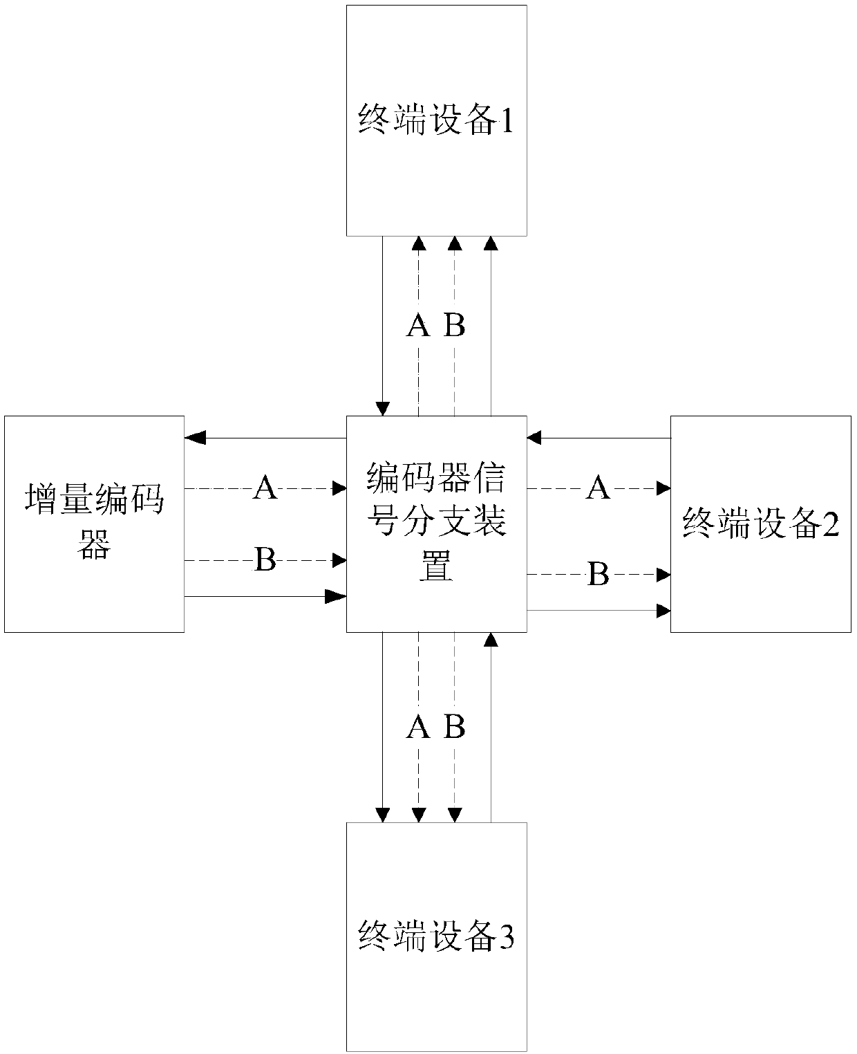
[0026] The encoder pulse signal branching device of the present invention has four interfaces, which are respectively used to connect one encoder and three terminal devices. The internal circuit and terminal device interface can be repeated as needed for expansion.

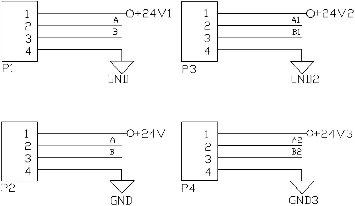
[0027] P1 is the encoder access port, which is connected to the encoder through a cable. The first terminal of the P1 terminal +24V1 is the encoder power supply terminal. The second and third terminals of the P1 terminal are the input terminals of the encoder pulse signal (A and B). , through the cable, input the pulse signal (A and B) of the encoder, the ④ end of the P1 terminal is the loop end of the encoder and the pulse signal. The P1 terminals are respectively conn...


PUM


Abstract

The invention, which relates to the technical field of the incremental encoders, discloses a loop signal branching device of an incremental encoder. The loop signal branching device is composed of a pulse square wave signal sampling circuit, an optoelectronic isolation transmission circuit and an encoder signal restoration circuit. The pulse square wave signal sampling circuit obtains a pulse signal square wave value outputted by an encoder and transmits the signal to the linear optoelectronic isolation transmission circuit to realize linear isolation transmission from a voltage signal to an optical signal and from an optical signal to a voltage signal. The voltage signal is transmitted to the encoder signal restoration circuit to realize outputting of two-phase square wave signals in thevirtual encoder pulse square wave loop. According to the invention, the two phases of pulse signals with the output phase difference of 90 degrees of the encoder are allocated to another terminal device, so that for different terminal devices and measurement and control systems, encoder signal sharing and application can be realized only by installing one encoder during same-physical variable measurement.

Description

technical field [0001] The present invention relates to the technical field of incremental encoders, and in particular to an incremental encoder loop signal branching device. Background technique [0002] In the automatic measurement and control environment, the device that converts physical signals such as rotation angle into electrical signals is called a signal encoder. Incremental encoders are the most widely used in industrial and automation environments. In addition to the working power supply, the output signal is two. A pulse signal (A and B) with a phase difference of 90 degrees. In industrial applications, 2 cores of the four-core signal cable are usually used to supply power to the encoder from the device terminal, and through the other 2 cores, the electrical signal output by the encoder is in the form of two pulse signals (A and B), transmitted to the device terminal (e.g. figure 1 ). [0003] Usually, the encoder and the terminal signal channel of the device...

Claims


Application Information

Patent Timeline
IPC IPC(8): G01D5/244
CPCG01D5/244
Inventor 蔺学华方志远
Owner XINJIANG GUANGLU ENERGY TECH CO LTD
Why Eureka
Try Eureka