
Damage detecting method of platy structure

A damage detection and plate shape technology, which can be used in measuring devices, analyzing solids using sonic/ultrasonic/infrasonic waves, and using sonic/ultrasonic/infrasonic waves for material analysis. and other problems to achieve the effect of weakening the impact, avoiding potential safety hazards, and improving the accuracy

Active Publication Date: 2018-04-17
CRRC QINGDAO SIFANG CO LTD
View PDF10 Cites 12 Cited by
  • Summary
  • Abstract
  • Description
  • Claims
  • Application Information

AI Technical Summary

Problems solved by technology

In the existing technology, in the method of detecting structural damage through piezoelectric transducers, since the detection environment is mostly indoors and the environmental conditions are relatively stable, the influence of temperature on the detection results is not considered, but the change of temperature will make the structure The phenomenon of thermal expansion and contraction occurs, which affects the propagation of waves in the structure to be detected, which in turn affects the accuracy of structural damage detection
[0003] When performing damage detection on key parts such as the EMU car body, due to the change of the external environment temperature or the temperature difference between the transformer in the working state and the transformer in the stopped state when the train is running, the key parts located around it The temperature of the structure also rises accordingly. At this time, if the damage detection of these key structures is carried out, the piezoelectric transducer is used for detection but the temperature factor is not considered, the detection accuracy will be affected, and there will be a large safety hazard.

Method used


Image

  • Damage detecting method of platy structure
  • Damage detecting method of platy structure
  • Damage detecting method of platy structure

Examples


Embodiment Construction

[0033] In order to enable those skilled in the art to better understand the technical solutions of the present invention, the present invention will be further described in detail below in conjunction with the accompanying drawings and specific embodiments.

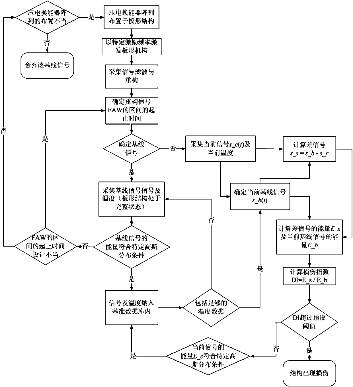
[0034] An embodiment of the present invention provides a damage detection method for a plate structure, the method includes the following steps:

[0035] S1: The piezoelectric transducer array is arranged in a plate-shaped structure;

[0036] S2: Establish a benchmark database:

[0037] (1) The piezoelectric transducer excites the undamaged plate-shaped structure at a specific excitation frequency to generate Lamb waves;

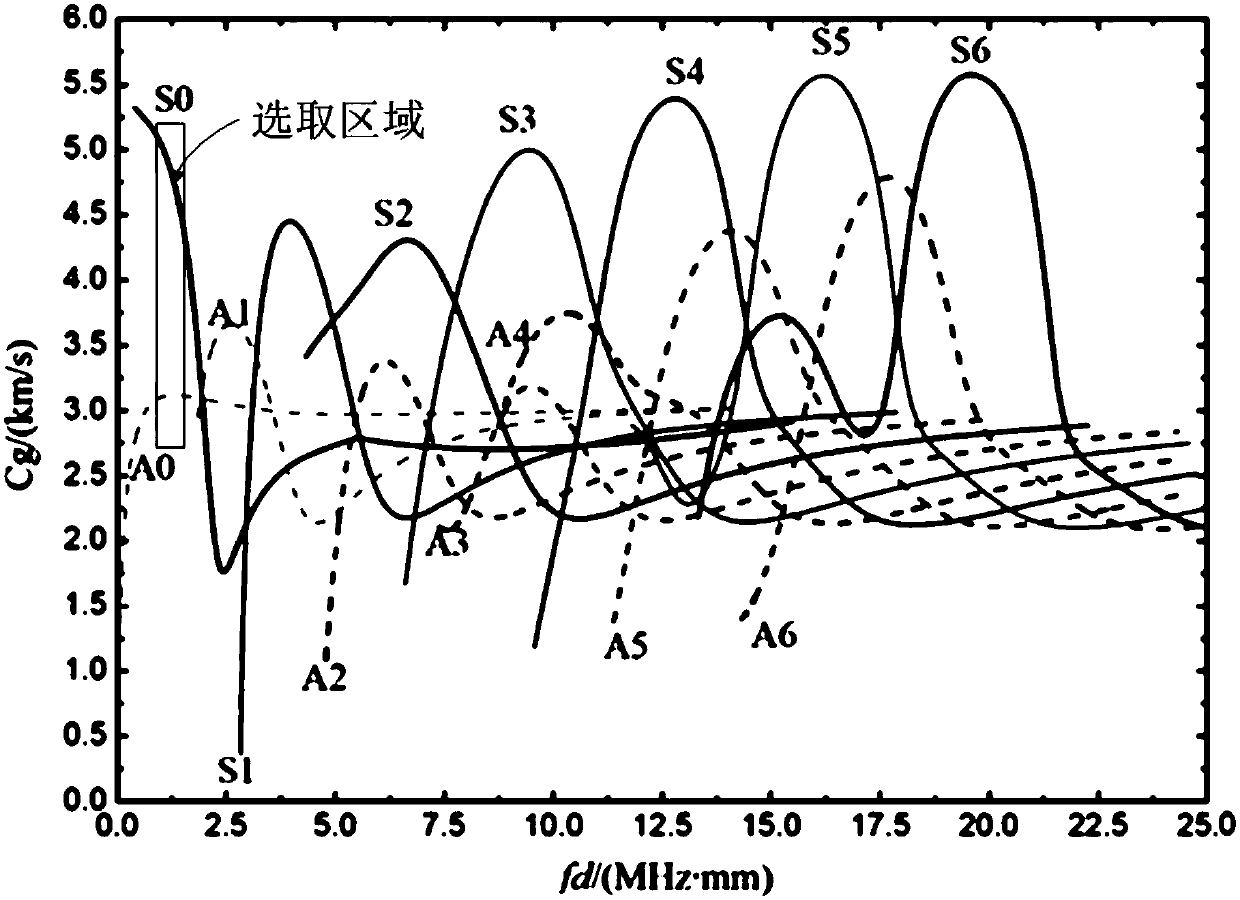
[0038] (2) collect multiple sets of baseline signals and their corresponding temperatures, each baseline signal is the eigenvalue of the first arriving wave of the Lamb wave;

[0039] (3) Store each group of baseline signals and their corresponding temperatures in the benchmark database;

[0040] S3:...


PUM


Abstract

The invention relates to a damage detecting method of a platy structure. The damage detecting method comprises the following steps of (S1) arranging a piezoelectric transducer array on the platy structure; (S2) establishing a benchmark database; (S3) collecting a current signal and a current temperature of the platy structure to be detected; (S4) calculating a difference signal which is equal to acurrent baseline signal in the benchmark database subtracts the current signal; (S5) calculating a damage index according to the difference signal and the current baseline signal, if the damage indexis greater than a preset threshold, judging that the platy structure to be detected is damaged, and if the damage index is no more than the preset threshold, judging that the platy structure to be detected is not damaged. The damage detecting method has the beneficial effects that due to adoption of a temperature compensation mode, the influence caused by larger temperature change is weakened inthe process of using piezoelectric transducers to detect the damage of the platy structure, so that the detection accuracy is improved and the potential safety hazards are avoided.

Description

technical field [0001] The invention relates to the technical field of structure detection, in particular to a damage detection method for a rail vehicle plate structure. Background technique [0002] At present, piezoelectric intelligent detection technology, as a kind of structural health detection technology, can carry out regional detection, is easy to integrate with structures, and is widely used in damage detection of composite materials and metal structures. In the existing technology, in the method of detecting structural damage through piezoelectric transducers, since the detection environment is mostly indoors and the environmental conditions are relatively stable, the influence of temperature on the detection results is not considered, but the change of temperature will make the structure The phenomenon of thermal expansion and contraction occurs, which affects the wave propagation in the structure to be detected, and then affects the accuracy of structural damage...

Claims


Application Information

Patent Timeline
IPC IPC(8): G01N29/04
CPCG01N29/041G01N2291/0234
Inventor 鞠增业马龙林鹏刘韶庆
Owner CRRC QINGDAO SIFANG CO LTD
Learn More