Liquid sample guiding device and detection equipment comprising same

A diversion device, liquid sample technology, applied in biological testing, material inspection products, instruments, etc., can solve the problems of easy generation of turbulence and air bubbles, affecting the repeatability of test results, etc., and achieve the effect of improving repeatability and reliability.

Inactive Publication Date: 2018-04-17
HELIXGEN GUANGZHOU
View PDF7 Cites 0 Cited by
  • Summary
  • Abstract
  • Description
  • Claims
  • Application Information

AI Technical Summary

Problems solved by technology

However, since the gas outlet of the cover plate is set directly above the reaction chamber, turbulence and air bubbles are likely to be generated when the sample flows from the sample chamber to the reaction chamber, thus affecting the repeatability of the test results

Method used


Image

  • Liquid sample guiding device and detection equipment comprising same
  • Liquid sample guiding device and detection equipment comprising same
  • Liquid sample guiding device and detection equipment comprising same

Examples


Embodiment 1

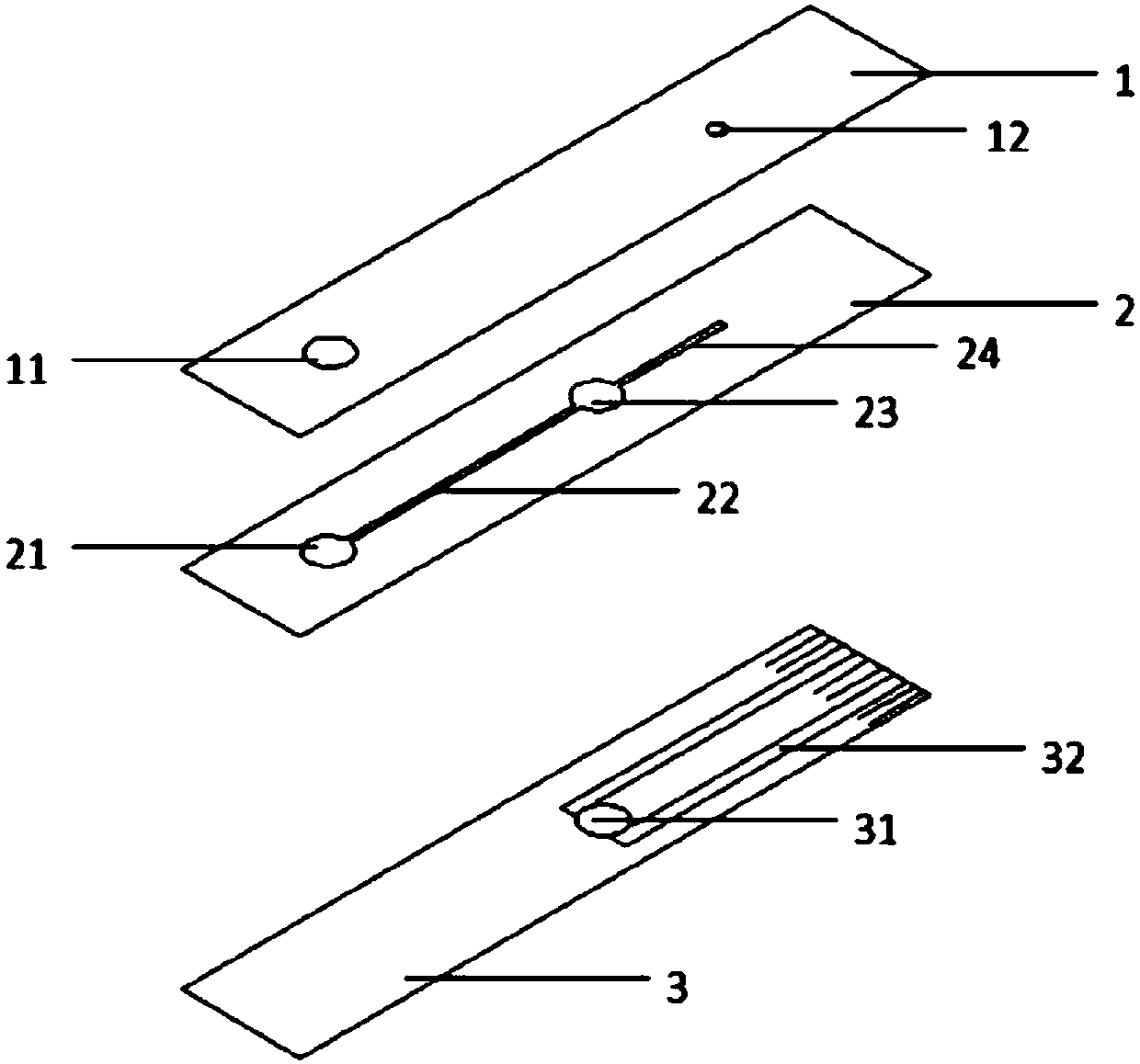
[0067] figure 2 It is a structural schematic diagram of the first embodiment of the present invention, that is, the structure of a liquid sample detection test strip. The components of the liquid sample detection test strip include a cover plate 1 , a channel plate 2 and a base plate 3 . Wherein, the sampling hole 11 is set at the left end of the cover plate 1 , and the air outlet 12 is set at the right end of the cover plate 1 . The channel plate 2 is provided with a sampling cavity 21 , a groove as a liquid circulation channel 22 and a circulation hole 23 . The groove is hollowed out. When the upper and lower surfaces of the channel plate are respectively stacked with the cover plate 1 and the base plate 3, the space defined by them together forms a circulation channel. One side wall of the channel is the lower surface of the cover plate, and the other side The wall is the upper surface of the substrate 3 . Wherein, the sampling cavity 21 is arranged at the left end of t...

Embodiment 2

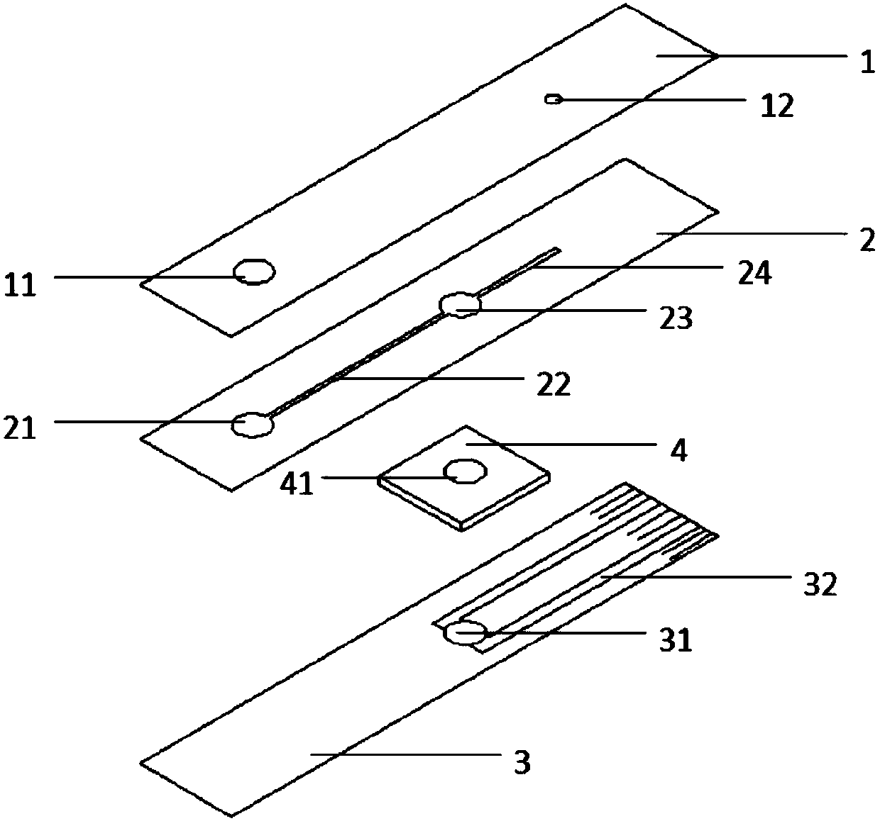
[0077] image 3 It is a schematic diagram of the structure of the second embodiment of the present invention. This embodiment is based on the above-mentioned embodiment 1 with the addition of a riser 4, which is also the structure used for liquid sample detection test strips. Specifically, the radial dimension of the spacer through hole 41 on the spacer 4 is the same as that of the flow hole 23 on the channel plate 2 and the reaction area 31 on the substrate 3 . The spacer 4 is fixed between the channel plate 2 and the base plate 3 by pasting, and makes the flow hole 23 , the through hole 41 of the spacer and the reaction area 31 be located on the same vertical plane. In a preferred embodiment, except the reaction area 31 is made of hydrophilic material, the rest of the substrate 3 is made of hydrophobic material. The riser 4 is used to limit the reaction area, so as to facilitate reagent spotting. When the amount of reagent required is large, the liquid will not overflow and...

Embodiment 3

[0079] Figure 4 It is a structural schematic diagram of the third embodiment of the present invention, which is also the structure used for liquid sample detection test strips. The difference from Embodiment 2 is that the air outlet 12 on the cover plate 1 is not located directly above the end of the extension pipe 24, but directly above the midpoint of the extension pipe 24. At this time, the air outlet 12 and the channel plate 2 define The air vent (not shown in the figure) is located at the midpoint of the extension duct 24, so that the extension duct 24 communicates with the outside world through the air vent defined by the air outlet 12. During the use of this embodiment, the air outlet at the middle point of the extension pipe 24 communicates with the outside world through the air outlet 12 on the cover plate 1 .

[0080] Through the setting in this way, the blood sample to be tested can be filled more uniformly and reliably from the sample chamber 21 through the liqui...


PUM

PropertyMeasurementUnit
Apertureaaaaaaaaaa

Abstract

The invention discloses a liquid sample guiding device and detection equipment comprising the same. The guiding device comprises a cover plate and a channel plate, wherein a sampling hole is formed inone end of the cover plate and an air outlet is formed in the other end; a sampling cavity, a liquid circulating channel and a circulating hole are formed in the channel plate, the sampling cavity islocated below the sampling hole and connected with the circulating hole through the liquid circulating channel, an extension pipeline extends out of the far end, relative to the sampling cavity, of the circulating hole in the channel plate, when the cover plate is stacked on the channel plate, the channel plate defines a vent port communicated with the outside through the air outlet, and the ventport is located at any pint of the extension pipeline or located at the further end, relative to the sampling cavity, of the tail end of the extension pipeline. The detection equipment also comprisesa base plate stacked with the cover plate and the channel plate to form a detection test strip. Besides, the detection equipment also comprises a detector comprising the detection test strip.

Description

technical field [0001] The invention relates to a real-time detection device for blood, in particular to a blood diversion device, a detection test strip, and a detection system containing the test strip. Background technique [0002] Point-of-care testing (POCT, point-of-care testing) refers to rapid clinical testing performed next to the patient, usually not necessarily performed by clinical examiners, but by nurses, doctors or even patients themselves. This is a new type of method that analyzes immediately at the sampling site, saves the complicated processing procedures of the specimens in the laboratory, and obtains the test results quickly. By definition, POCT is a detection method that is carried out at the sampling site and uses portable analytical instruments and supporting reagents to quickly obtain test results. [0003] In recent years, POCT has been widely used, including various departments of hospitals, primary hospitals, community clinics and families, such ...

Claims


Application Information

Patent Timeline
IPC IPC(8): G01N35/10G01N33/86G01N33/66
CPCG01N33/66G01N33/86G01N35/10
Inventor 赵天贤张仑曾庆许文文
Owner HELIXGEN GUANGZHOU
Why Eureka
Try Eureka