Apparatus for driving optical-reflector

一种光学反射、设备的技术,应用在光学、光学元件、仪器等方向,能够解决不保证精确的控制等问题,达到简单结构、提高空间利用率、降低不良率的效果

Active Publication Date: 2018-04-17
JAHWA ELECTRONICS
View PDF6 Cites 11 Cited by
  • Summary
  • Abstract
  • Description
  • Claims
  • Application Information

AI Technical Summary

Problems solved by technology

However, in this method, the load of the optical reflector or the support to which the optical reflector is coupled is applied in a specific direction, so the strength of the driving power is not functionally proportional to the movement of the optical reflector, but rather The optical reflector is driven intermittently, which does not guarantee precise control

Method used


Image

  • Apparatus for driving optical-reflector
  • Apparatus for driving optical-reflector
  • Apparatus for driving optical-reflector

Examples


Embodiment Construction

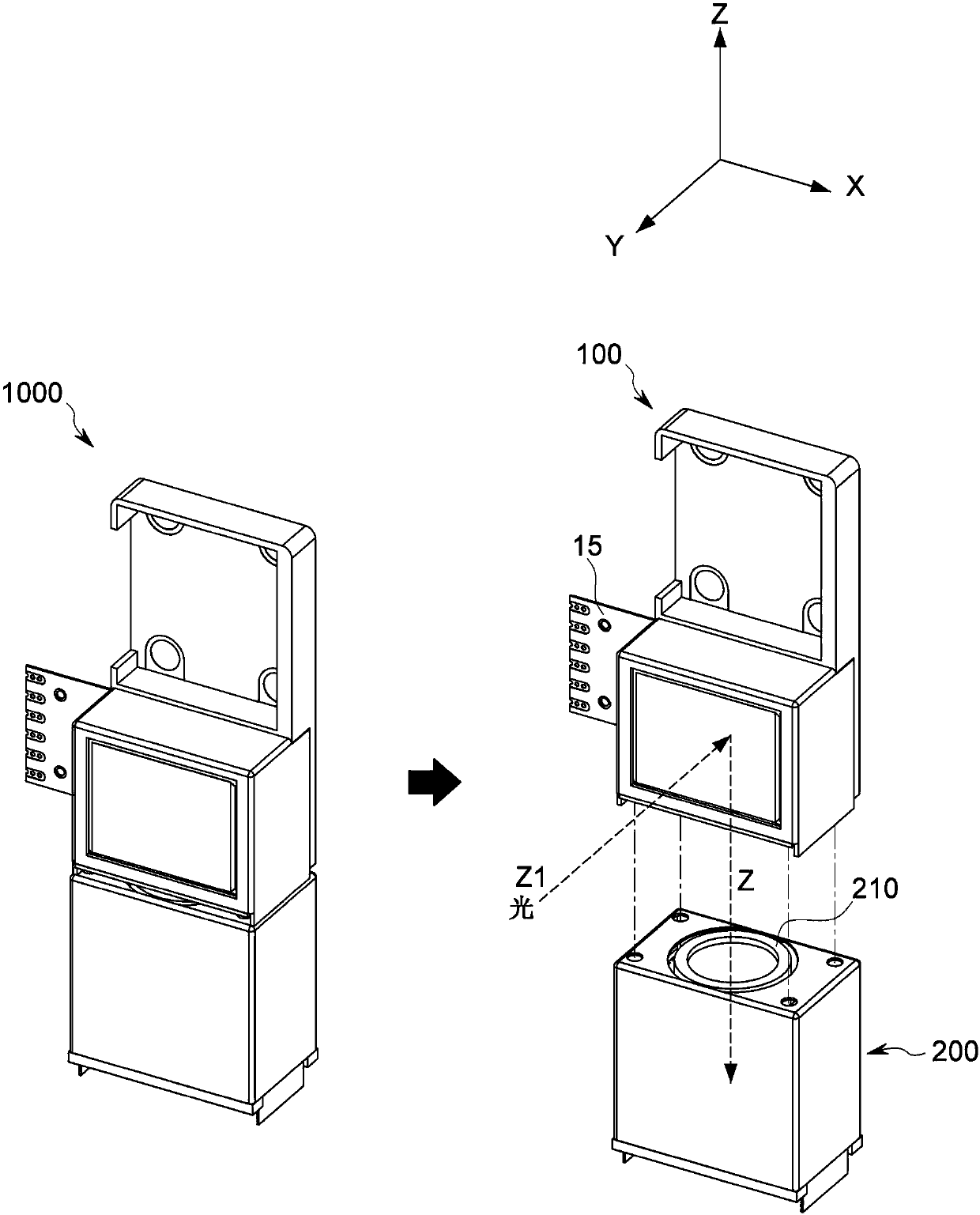
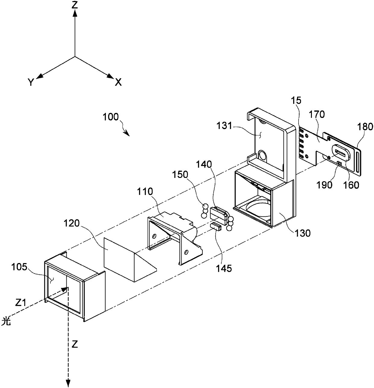
[0043] figure 1 is a diagram illustrating an overall configuration of an apparatus 100 for driving an optical reflector (hereinafter, also referred to as a “driving apparatus”) and an actuator 1000 to which the driving apparatus is applied according to an embodiment of the present disclosure.

[0044] The driving device 100 of the present disclosure may be realized as a single device, or may also be realized as a component of a single actuator 1000 so as to be coupled with the upper part of the lens driving unit 200 including a lens (zoom lens) 210 and A unit for performing an auto focus (AF) operation on the lens 210, a unit for performing optical image stabilization (OIS) along one axial direction, or a unit for simultaneously performing an AF operation and an OIS operation along one axial direction ,like figure 1 shown in .

[0045] In the present disclosure, the light of an object or the like is not directly input to the lens 210, but the light is routed by the optical r...


PUM


Abstract

An apparatus for driving an optical-reflector includes a support frame having a groove portion line formed therein; a reflectometer installed in the support frame, and causing light to enter a lens bychanging the path of light that has entered through an opening portion; a base frame having a guide groove portion having a shape corresponding to the groove portion line; a plurality of balls disposed between the groove portion line and the guide groove portion so that the support frame and the base frame are kept spaced apart from each other; and a driving part moving the support frame along apath that corresponds to the groove portion line or the guide groove portion.

Description

technical field [0001] The present disclosure relates to an apparatus for driving an optical reflector, and more particularly, to an improvement in optical image stabilization (OIS) precision by applying a structure in which the optical reflector is rotated using a guide having a rounded shape or the like Device for driving optical reflectors for optical image stabilization. Background technique [0002] With the development of hardware technology, changes in user environments, etc., various complex functions are integrally implemented at mobile terminals such as smart phones in addition to basic functions for communication. [0003] A representative example is a camera module having an auto focus (AF) function and an optical image stabilization (OIS) function. In addition, a voice recognition function, a fingerprint recognition function, an iris recognition function, etc. are loaded on a portable terminal for authentication or security, and mounting a zoom lens grouping a ...

Claims


Application Information

Patent Timeline
Patent Type & Authority Applications(China)
IPC IPC(8): G02B7/182H04N5/232G06K9/20G06K9/00
CPCG02B7/1821G06V40/10G06V10/145G06V10/147H04N23/685H02K11/215G02B27/646H02K33/16H02P6/006
Inventor 延济丞李柄徹姜秉佶朴铁顺
Owner JAHWA ELECTRONICS
Why Eureka
Try Eureka