Light-emitting diode driving system with fast voltage adjustment circuit

A technology of voltage adjustment circuit and light-emitting diode, which is applied in the direction of electroluminescence light source, electric light source, light source, etc., and can solve the problems of error-prone and insufficient speed of light-emitting drive signals

Active Publication Date: 2019-05-24
SEMISILICON TECH
View PDF5 Cites 0 Cited by
  • Summary
  • Abstract
  • Description
  • Claims
  • Application Information

AI Technical Summary

Problems solved by technology

At present, the disadvantage of generating the plurality of pulses in the LED driving system of the related art is that the speed of generating low voltage or high voltage in the LED driving system of the related art is not fast enough, so that the light-emitting driving signal is prone to error

Method used


Image

  • Light-emitting diode driving system with fast voltage adjustment circuit
  • Light-emitting diode driving system with fast voltage adjustment circuit
  • Light-emitting diode driving system with fast voltage adjustment circuit

Examples


Embodiment Construction

[0054] The present invention is further described below with reference to the accompanying drawings and specific embodiments, so that those skilled in the art can better understand the present invention and implement it, but the embodiments are not intended to limit the present invention.

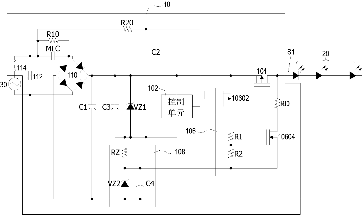
[0055] Please refer to figure 1 , which is the circuit diagram of the first embodiment of the light emitting diode drive system with fast voltage adjustment circuit of the present invention. An LED driving system 10 with a fast voltage regulation circuit is used to drive a plurality of two-pin point-controlled LED lamps 20 and is connected to an AC power supply device 30 .

[0056] The LED driving system 10 with a fast voltage regulation circuit includes a control unit 102, an output switch unit 104, a fast voltage regulation circuit 106, a light-emitting signal voltage generation circuit 108, a first capacitor C1, and a second capacitor C2, a third capacitor C3, a control terminal zener ...


PUM


Abstract

The invention discloses a light emitting diode driving system with a fast voltage adjustment circuit, comprising a control unit, an output end switch unit, a fast voltage adjustment circuit and a light emitting signal voltage generation circuit. When the control unit does not turn on the output switch unit, the control unit controls the fast voltage adjustment circuit to process an output voltage, and the light-emitting signal voltage generation circuit cooperates with the fast voltage adjustment circuit to clamp the output voltage to satisfy a Default value; when the output voltage is processed to meet the default value, the control unit turns on the output switch unit to restore the output voltage and generate a light-emitting driving signal; a plurality of two-pin point-controlled LED lamps emit light according to the The driving signal operates in the light-emitting mode. The present invention can quickly discharge or boost the voltage to generate the light-emitting driving signal quickly and correctly.

Description

technical field [0001] The invention relates to a light-emitting diode drive system, in particular to a light-emitting diode drive system with a fast voltage adjustment circuit. Background technique [0002] The LED drive system in the related art is a common electronic device; the LED drive system in the related art is used to generate a light-emitting drive signal and transmit the light-emitting drive signal to a plurality of LED lamps to drive the LED lamps to emit light; therefore, the related art LED drive system is very important. [0003] The light-emitting driving signal generated by the LED driving system in the related art usually includes a plurality of pulse waves; the plurality of pulse waves include high voltage and low voltage. At present, the disadvantage of generating the plurality of pulses in the related art LED driving system is that the speed of the related art LED driving system to generate low voltage or high voltage is not fast enough, so that the li...

Claims


Application Information

Patent Timeline
Patent Type & Authority Patents(China)
IPC IPC(8): H05B33/08H05B44/00
CPCH05B45/00H05B45/37Y02B20/30
Inventor 彭文琦
Owner SEMISILICON TECH
Why Eureka
Try Eureka