Vehicle light and method for providing a light function by means of a vehicle light

A technology of light function and car lights, which is applied in the field of car lights, can solve the problem of not being aware of a uniform lighting surface, and achieve the effect of improving visibility

Active Publication Date: 2018-04-17
VOLKSWAGEN AG
View PDF14 Cites 2 Cited by
  • Summary
  • Abstract
  • Description
  • Claims
  • Application Information

AI Technical Summary

Problems solved by technology

Due to the shape of the facets of the decoupling structure, a flash effect is produced by means of optical elements, in which the observer does not perceive a homogeneous illuminated surface in the case of varying viewing positions and viewing angles

Method used


Image

  • Vehicle light and method for providing a light function by means of a vehicle light
  • Vehicle light and method for providing a light function by means of a vehicle light
  • Vehicle light and method for providing a light function by means of a vehicle light

Examples


Embodiment Construction

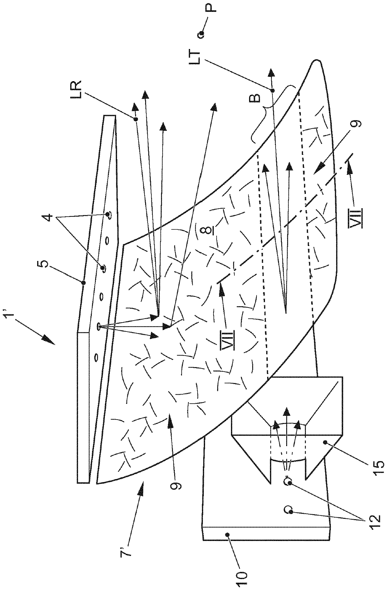
[0072] refer to figure 1 Explain the basic structure of the car light 1:

[0073] The vehicle light 1 is accommodated in a housing 2 which is closed by a transparent outer disc 3 in the direction of light radiation of the vehicle light 1 . The vehicle light 1 comprises at least three light sources 4 which are arranged on a printed circuit board 5 and which are actuated or controllable by means of a control unit 6 . The light sources 4 are arranged at various positions, as will be explained in more detail below. The light source 4 is in particular a light emitting diode. An optical element 7 is arranged in the light emission direction of the light source 4 . In the present embodiment, the optical element 7 is a reflector 7 , especially an associated reflector 7 . This reflector 7 has a reflector surface 8 which faces the light source 4, so that the light beam emitted by the light source 4 falls on the reflector surface 8 and can pass through the outer optical disk 3 outward...


PUM


Abstract

The invention relates to a vehicle light (V) having at least one optical element (7') which comprises a multiplicity of facet faces (9), wherein the directions of light beams which can be emitted in the direction of the optical element (7') can be changed by means of the facet faces (9). According to the invention it is proposed that the optical element (7') be assigned a plurality of light sources (4), wherein the light sources (4) can be actuated and are arranged relative to the positions and/or orientations of the facet faces (9) in such a way that light beams emitted by the light sources (4) are reflected (LR) at the optical element (7') and a twinkling effect can be perceived from a specific observation position (P), wherein the optical element (7') is of transparent design, and at least one further light source (12) is present on a side of the optical element (7') facing away from the observation position (P), through which side light beams (LT) passing through the optical element (7') in the direction of the observation position (P) can be emitted. As a result, it is possible to provide a vehicle light with which a plurality of light functions can be generated easily and which has a particularly characteristic appearance during operation.

Description

technical field [0001] The invention relates to a vehicle lamp with the features of the preamble of claim 1 . The invention also relates to a method for providing a light function by means of a vehicle light. Background technique [0002] Such a vehicle light is known from DE 10 2012 005 826 A1. Specifically, the optical element has a light coupling-in surface for coupling-in the light radiation of the light source and a decoupling structure, in which the direction of the coupled-in light beam is changed in such a way that an illumination characteristic is produced which is similar to the light radiation of the light source of the vehicle lamp The radiation characteristics are different. The decoupling structure includes a plurality of facets in which the light beams are decoupled at an illumination angle that is related to the respective angular orientation of the facets. The facets are arranged at different angles to each other in a non-repeating pattern. Due to the sh...

Claims


Application Information

Patent Timeline
Patent Type & Authority Applications(China)
IPC IPC(8): F21S41/10F21S41/32F21S41/37F21S43/10F21S43/31F21S43/33F21W107/10F21Y115/10
CPCB60Q1/2607F21S43/14F21S43/26F21S43/31F21W2103/10
Inventor C.施图德尼M.米勒
Owner VOLKSWAGEN AG
Why Eureka
Try Eureka