Car body flexible positioning fixture mechanism used for aluminum alloy head cover laser welding of lightweight car body

A flexible positioning and laser welding technology, used in laser welding equipment, welding equipment, manufacturing tools, etc., can solve the problems of increased plate clearance, difficulty in ensuring the Y-direction accuracy of the vehicle side wall, and welding seam offset, etc. Wide range, high practical value, and small installation footprint

Active Publication Date: 2018-04-20
ANHUI JEE AUTOMATION EQUIP CO LTD
View PDF6 Cites 4 Cited by
  • Summary
  • Abstract
  • Description
  • Claims
  • Application Information

AI Technical Summary

Problems solved by technology

[0005] 1. There is no locking mechanism in the lateral direction of the laser welding area. After the top cover fixture 3' is pressed down, due to the Y-direction deformation of the side wall, the weld seam will shift, and the gap between the plates will increase, which will easily cause weld sags and weld seams. Defects such as offset and pores;
[0006] 2. After the welding is completed, the Y-direction accuracy of the side wall of the vehicle is difficult to guarantee;
[0007] 3. Failure to meet the flexible switching of multiple models

Method used


Image

  • Car body flexible positioning fixture mechanism used for aluminum alloy head cover laser welding of lightweight car body
  • Car body flexible positioning fixture mechanism used for aluminum alloy head cover laser welding of lightweight car body
  • Car body flexible positioning fixture mechanism used for aluminum alloy head cover laser welding of lightweight car body

Examples


Embodiment Construction

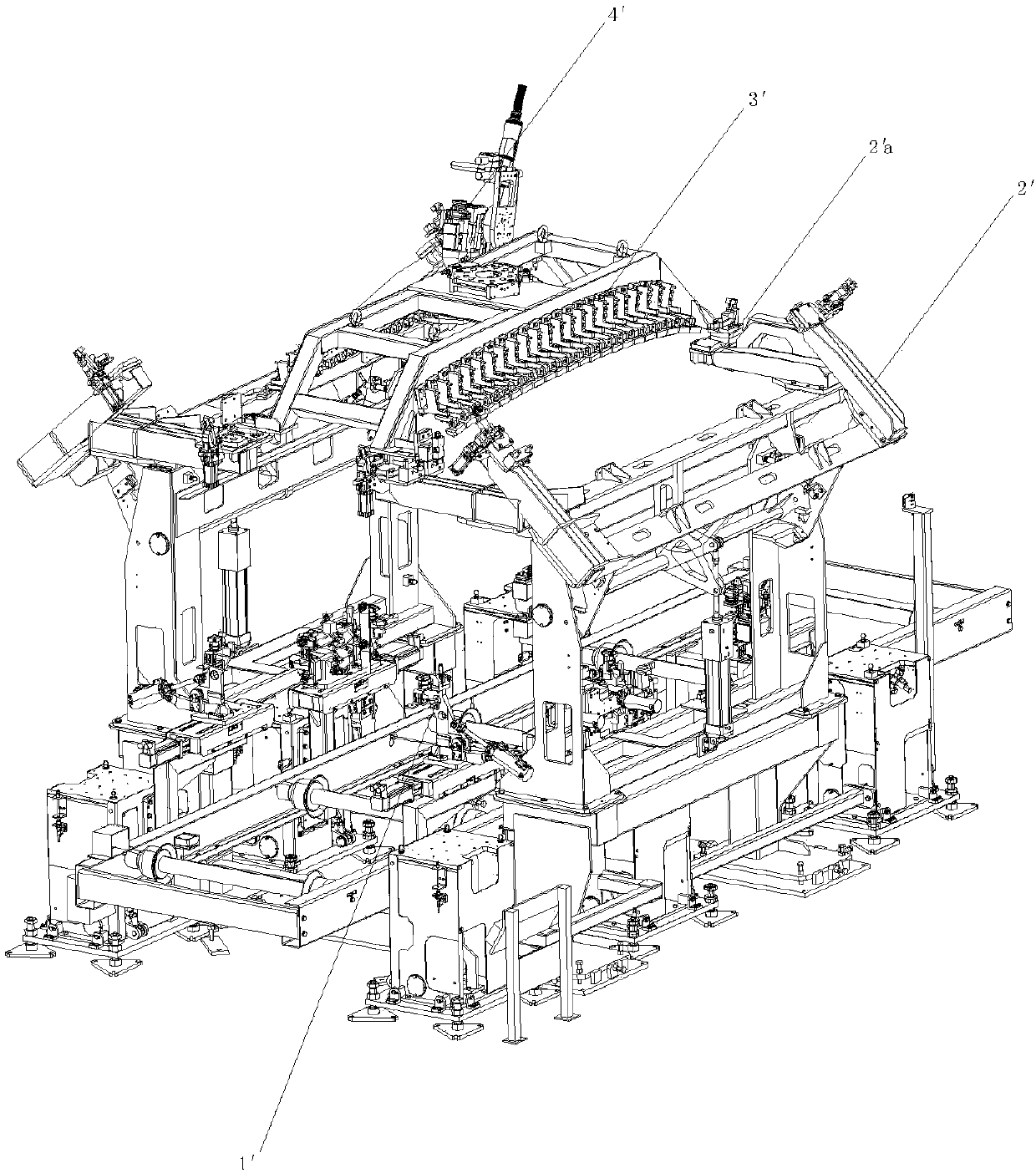
[0033] The following describes in detail the specific implementation of the flexible positioning fixture mechanism of the light-weight aluminum alloy roof cover laser welding body of the present invention with reference to the accompanying drawings.

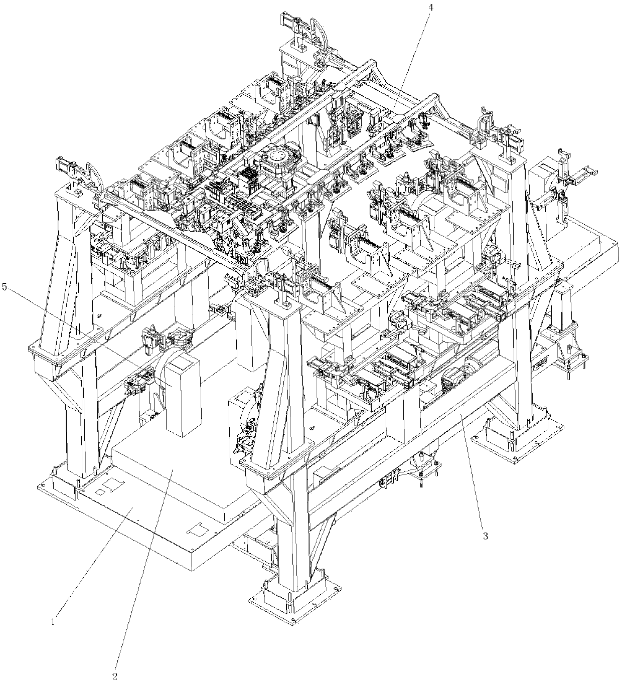
[0034] Please refer to figure 2 , the flexible positioning fixture mechanism of the lightweight aluminum alloy roof cover laser welding body of the present embodiment has the following structure:

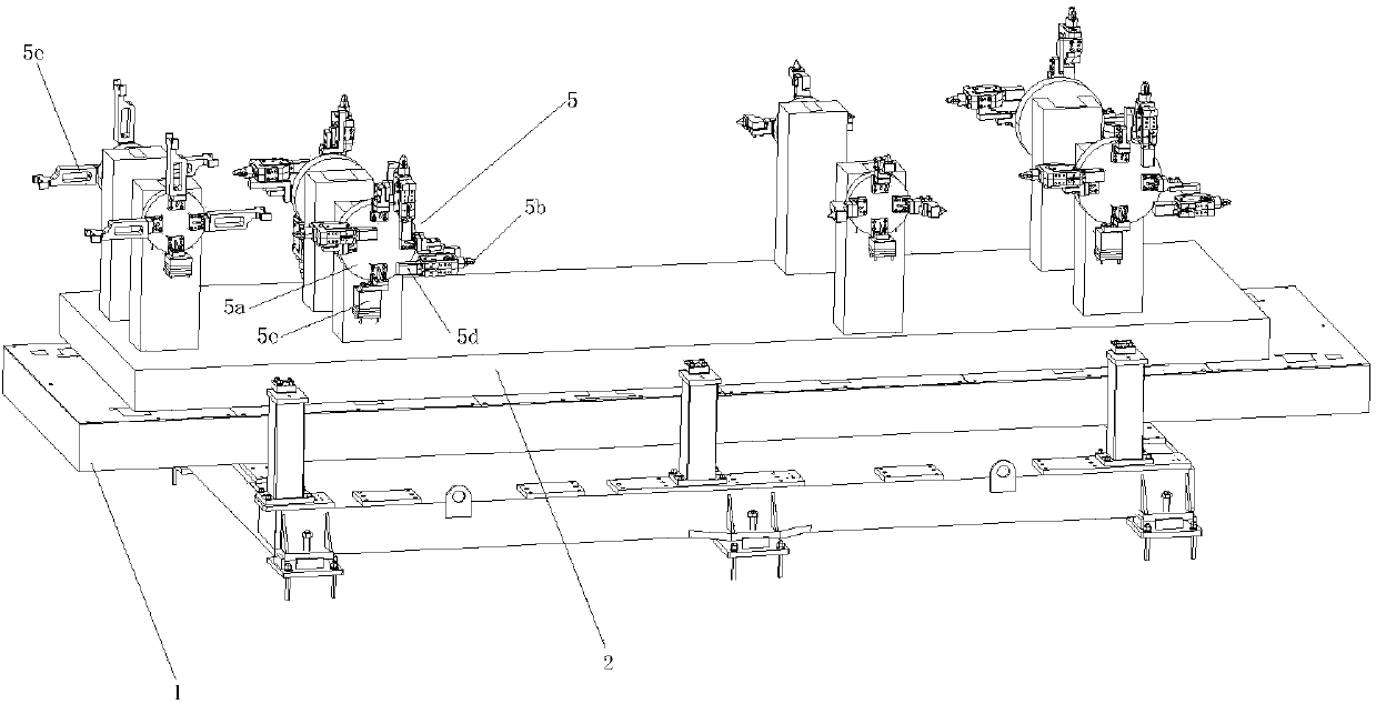
[0035] Such as image 3 As shown, a flexible trolley 1 is set, and the flexible trolley 1 is transported to the laser welding station by means of the high-speed roller bed 2 below it, and multiple groups of windmill disk flexible switching devices 5 are arranged symmetrically on the left and right sides of the upper end of the flexible trolley 1, in different positions A plurality of positioning pins 5b or a plurality of support blocks 5c adapted to the bottom end structure of each vehicle body are set on the switching flange 5a of t...


PUM


Abstract

The invention provides a car body flexible positioning fixture mechanism used for aluminum alloy head cover laser welding of a lightweight car body. The car body flexible positioning fixture mechanismis provided with a flexible trolley and a high-speed roller bed, multiple sets of windmill plate flexible switching devices are symmetrically arranged on the left and on the right of the upper end ofthe flexible trolley, and locating pins and supporting blocks on the windmill plate flexible switching devices form location and support for the bottom end of the car body. A pair of lateral positioning locking mechanisms are symmetrically arranged on the left and on the right of the high-speed roller bed, single positioning locking mechanisms are arranged at the positions, corresponding to car body side body stand column laser welding areas, of a supporting frame of each lateral positioning locking mechanism, and side body outer plate positioning blocks and side body inner plate positioningblocks of the ingle positioning locking mechanisms are matched to form positioning and locking of a car body side body in the Y direction. A head cover fixture is disposed on a car body head cover, the two sides of the head cover fixture are locked through a pressing mechanism, and positioning and clamping of the car body head cover are realized. According to the car body flexible positioning fixture mechanism, the car body can be precisely positioned, the high requirements of laser welding for car body position precision are met, and meanwhile multiple-vehicle-model switching can be realized.

Description

technical field [0001] The invention relates to a welding jig, more specifically a welding jig for a body in white, especially a flexible positioning jig mechanism used in laser welding of a top cover and a side wall. Background technique [0002] With the popularization and application of laser welding technology in the manufacture of aluminum alloy bodywork, the requirements for the quality of weld seams in laser welding of automobile roofs are also gradually increasing. In the roof-side laser welding application, the welding quality is closely related to the gap control between the plates. [0003] Traditional laser welding fixture positioning mechanism such as figure 1 shown. After the car body is transported to the laser welding station using a skid, it is lifted using a positioning fixture 1'; after positioning, the cylinder pushes the lateral turning mechanism 2' to reach the limit, such as figure 1 The state shown in middle 2'a; the robot places the top cover fixt...

Claims


Application Information

Patent Timeline
Patent Type & Authority Applications(China)
IPC IPC(8): B23K26/70
CPCB23K26/70
Inventor 刘蕾刘宏婕汤东华成子文李伟王静
Owner ANHUI JEE AUTOMATION EQUIP CO LTD
Why Eureka
Try Eureka