
Hydraulic pressure suspension polishing fixed-point fluid pressure detecting system

A technology of fluid pressure and detection system, which is applied in the direction of grinding/polishing equipment, control of workpiece feed movement, grinding machine tool components, etc., to achieve high accuracy and solve the effect of entanglement problems

Pending Publication Date: 2018-04-20
ZHEJIANG UNIV OF TECH
View PDF7 Cites 5 Cited by
  • Summary
  • Abstract
  • Description
  • Claims
  • Application Information

AI Technical Summary

Problems solved by technology

Although the pressure time change has certain reference value, it is not the pressure of the target fixed point (workpiece position)
Moreover, the sensor is arranged at the bottom of the container and measures the liquid pressure near the bottom of the container. Due to the thickness of the polishing liquid film, there is a certain deviation from the actual pressure at the workpiece patch that needs to be measured.

Method used


Image

  • Hydraulic pressure suspension polishing fixed-point fluid pressure detecting system
  • Hydraulic pressure suspension polishing fixed-point fluid pressure detecting system
  • Hydraulic pressure suspension polishing fixed-point fluid pressure detecting system

Examples


Embodiment Construction

[0018] The present invention will be further described below in conjunction with the accompanying drawings.

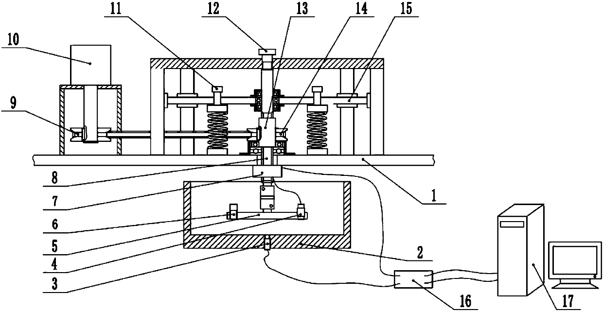
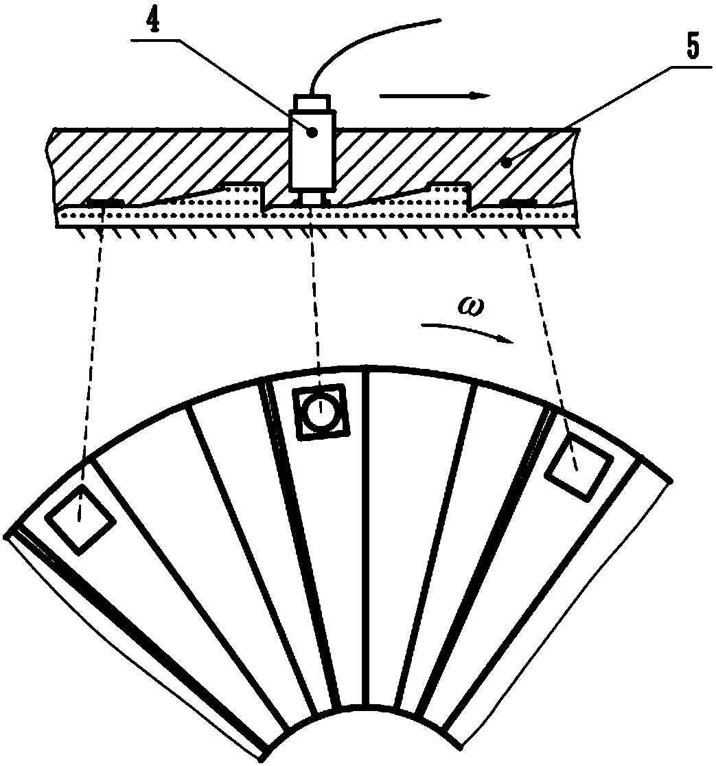
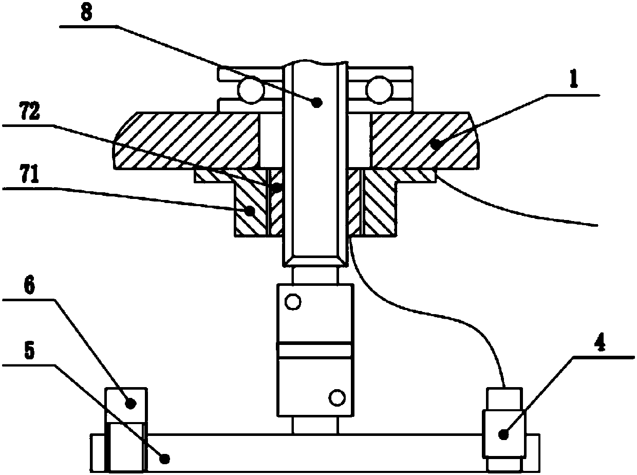
[0019] refer to Figure 1 ~ Figure 3 , a hydraulic pressure suspension polishing fixed-point fluid pressure detection system, including a pressure sensor 4, a balance adjustment screw 6, a signal conditioning amplifier, a conductive slip ring 7, an acquisition card 16 and a computer 17. The parallel area below the polishing tool disk 5 has a groove, and a workpiece is pasted in the groove. One of the workpiece positions is drilled together with the polishing tool disk 5, and the pressure sensor 4 for hydraulic pressure measurement is fixed on the workpiece drilled position from top to bottom. On the symmetrical side of the workpiece position, the balance adjustment stud 6 is fixed in the same way. The conductive slip ring 7 is installed on the ball spline shaft 8 , the inner ring 71 of the conductive slip ring cooperates with the ball spline shaft, and the outer ring...


PUM


Abstract

The invention discloses a hydraulic pressure suspension polishing fixed-point fluid pressure detecting system. In a hydraulic pressure suspension polishing device, a groove is formed in the parallel area below a polishing tool disc and internally pasted with workpieces, and the polishing tool disc is mounted at the lower end of a ball spline shaft. The hydraulic pressure suspension polishing fixed-point fluid pressure detecting system comprises pressure sensors, balance adjusting studs and an electric conduction slipping ring. Holes are formed in the position of one of the workpieces and the polishing tool disc, the pressure sensors used for hydraulic pressure measuring are fixed to the position of the workpiece from top to bottom, and the balance adjusting studs are fixed to the positionsof the symmetrical sides of the workpiece in the same mode. The balance adjusting studs and the pressure sensors are equal in weight and rotary inertia. The electric conduction slipping ring is mounted on the ball spline shaft, and an inner ring of the electric conduction slipping ring is matched with the ball spline shaft. An outer ring of the electric conduction slipping ring is fixed to the bottom of a middle supporting plate. Connecting wires of the inner ring of the electric conduction slipping ring are connected with the pressure sensors, and connecting wires of the outer ring of the electric conduction slipping ring are the data output ends. According to the hydraulic pressure suspension polishing fixed-point fluid pressure detecting system, the accuracy is high.

Description

technical field [0001] The invention relates to the field of non-contact polishing fluid pressure detection, in particular to a detection system for hydrodynamic pressure suspension polishing fluid pressure. Background technique [0002] The hydrodynamic suspension polishing method is a polishing method applied to the atomic-level ultra-smooth and low-damage surface processing. In the process of hydrodynamic suspension polishing, the polishing tool disc is driven by the servo motor to rotate and drive the liquid to flow. The flowing liquid will generate a liquid pressure effect on the sample stuck to the bottom surface of the polishing tool disc. The size of the liquid pressure and Distribution has a significant impact on the surface material removal rate and surface uniformity of the specimen. Therefore, the pressure measurement of the workpiece area during the polishing process is one of the very effective means to study its mechanism of action. [0003] In an existing m...

Claims


Application Information

Patent Timeline
Patent Type & Authority Applications(China)
IPC IPC(8): B24B1/00B24B49/00
CPCB24B1/00B24B49/00
Inventor 尹林志文东辉朴钟宇吴晓峰薛凯元
Owner ZHEJIANG UNIV OF TECH
Learn More