[0023] The technical solutions in the embodiments of the present invention will be clearly and completely described below in conjunction with the accompanying drawings in the embodiments of the present invention. Obviously, the described embodiments are only part of the embodiments of the present invention, not all of them. Based on the implementation manners in the present invention, all other implementation manners obtained by persons of ordinary skill in the art without making creative efforts belong to the scope of protection of the present invention.
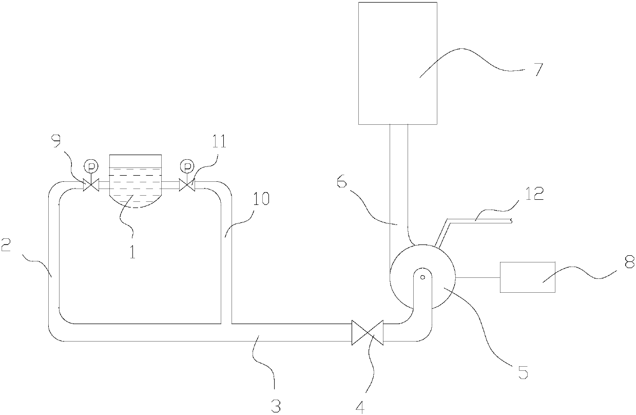
[0024] see Figure 1 to Figure 2 A preferred embodiment of the present invention provides a slurry treatment system, including a settling tank 1 for settling sludge, the bottom of the settling tank 1 leads to a first pipeline 2, and the first pipeline 2 is connected to the second Two pipelines 3, the second pipeline 3 is connected to the inlet of the slurry pump 5 through the first valve 4, the outlet of the slurry pump 5 is connected to the third pipeline 6, and the third pipeline 6 connects the slurry pump 5 The sent slurry is sent to the solid-liquid separation device 7, and the slurry pump 5 is connected to a motor 8, and the power of the motor 8 is variable, so that the flow rate of the slurry sent by the slurry pump 5 is variable.
[0025] In this embodiment, by setting the power of the motor 8 to be variable, the flow rate of the slurry sent by the slurry pump 5 can be adjusted according to production needs, so that the solid-liquid separation device 7 can be utilized to the maximum extent, and the slurry processing efficiency can be improved.
[0026] Wherein, in order to clearly express the technical solution of the present invention, due to figure 1 The size of each equipment shown in the figure is quite different, therefore, it is not drawn according to the actual scale, and it is specially explained here: the settling tank 1 is the equipment for storing mud in the slurry treatment system. Generally speaking, the size of the settling tank 1 is relatively small. Larger pipes with a diameter of more than 10 meters are also common, while the diameters of individual pipes in the system are generally less than 0.5 meters.
[0027] Settling tank 1 is generally equipped with a device to accelerate the sedimentation of the mud, and the mud sinks into the bottom of the tank, which can be a curved bottom or a flat bottom. The settling tank 1 is generally a cylindrical barrel-shaped building built on the ground, which can be a reinforced concrete structure. The visible position on the ground is the outer wall surface of the settling tank 1, and the position where the first pipeline 2 leads from the bottom of the settling tank 1 is The lower edge of the outer wall surface of the settling barrel 1 is close to the ground. Of course, in another embodiment, the settling tank 1 can also be an integrated device, and it is assumed to be on a support. At this time, the position of the first pipeline 2 drawn from the settling tank 1 can be the arc of the settling tank 1. surface or flat bottom.
[0028] The first pipeline 2 is made of steel, which has strong properties of anti-compression and anti-wear, and can cope with the erosion and pressure of the mud inside the pipeline.
[0029] The second pipeline 3 is made of steel, which has strong compression and wear resistance properties, and can cope with the erosion and pressure of the mud inside the pipeline. The diameter of the second pipeline 3 is generally slightly larger than the first pipeline 2, and the connection mode between the first pipeline 2 and the second pipeline 3 can be welding, and pipe joints can also be used, such as using end straight joints, straight joints, tee joints, elbow joints, etc. Heads, joints with living nuts, hinged joints, plugs, transition joints, etc.
[0030] The function of the first valve 4 is to shut off the third pipeline 3 to deliver mud to the slurry pump 5, and the first valve 4 can be selected from a gate valve, a stop valve, a ball valve and a butterfly valve.
[0031] The slurry pump 5 can be a ZJ type slurry pump, that is, a horizontal axial suction single-stage single-suction centrifugal slurry pump, which is characterized in that the outlet position of the pump can be rotated at 45° intervals to install and use at eight different angles. The inlet of the slurry pump 5 is the center of the pump body, and the outlet of the slurry pump 5 is the position along the tangent direction of the outer circumference. The slurry pump 5 has an impeller inside, and the rotation of the impeller exerts pressure on the slurry, so that the slurry is under the centrifugal force. Under the action, it is sprayed out from the outlet of mud pump 5.
[0032] The third pipe 6 is similar to the first pipe 2 or the second pipe 3 and also has the characteristics of anti-pressure and anti-wear.
[0033] The solid-liquid separation device 7 is generally set as a workstation, which includes a plurality of filter presses (not shown), the mud passes through the pressure of the filter press platen, the water is separated, and the mud between the filter press platens forms a mud cake , the pressure plate of the filter press releases pressure, the mud cake falls off, and the required mud can be obtained, and the separated water can flow into the settling tank 1 again for recycling, and the solid-liquid separation of the mud is completed since then.
[0034] The output shaft of the motor 8 is connected with a reduction mechanism (not shown), and transmits power to the slurry pump 5 to drive the impeller of the slurry pump 5 to rotate.
[0035] Further, the motor 8 is electrically connected to a frequency converter, and the slurry processing system further includes a PLC controller, and the PLC controller is electrically connected to the frequency converter. The parameters of the frequency converter are controlled by the PLC controller, so that the frequency converter changes the parameters such as the voltage and frequency of the input motor, and the output power of the motor 8, thereby changing the rotation speed of the impeller of the slurry pump 5, so that the slurry pump 5 sends out The flow rate of the mud changes.
[0036] Further, the first pipeline 2 is provided with a second valve 9, the second valve 2 is electrically connected to the PLC controller, and the PLC controller controls the opening and closing of the second valve 2. The function of the second valve 9 is to shut off the transport of the mud in the settling tank 1 from the first pipeline 2 . Using a PLC controller to control the opening and closing of the second valve 9 has a high degree of automation and reduces the labor intensity of manual opening and closing.
[0037]Further, the bottom of the settling tank 1 is provided with a fourth pipeline 10, the fourth pipeline 10 is connected to the second pipeline 3, the fourth pipeline 10 is provided with a third valve 11, and the third valve 11 It is electrically connected with the PLC controller, and the PLC controller controls the opening and closing of the third valve 11 . As mentioned above, the size of the settling tank 1 is much larger than the size of each pipeline, and there are many muds settled in the settling tank 1. In order to speed up the efficiency of slurry treatment, a fourth pipeline 10 is added. The fourth pipeline 10 can be arranged far away from the first A position of the pipe 2 , for example, a position symmetrical to the center of the settling tank 1 . In other embodiments, the number of additional pipelines can be more than 2, and each pipeline should be evenly distributed in the surrounding area of the settling tank 1, for example, in a preferred embodiment, the first pipeline 1 and the fourth pipeline 10 are included Inside, there are 5 pipelines distributed around the settling tank 1 , and the 5 pipelines are all collected into the second pipeline 3 .
[0038] Further, the second valve 9 and the third valve 11 are pneumatic valves. The telescopic movement of the cylinder of the pneumatic valve drives the movement of the actuator in the valve body to realize the shutoff of the first pipeline 9 and the fourth pipeline 11 . In other embodiments, the second valve 9 and the third valve 11 may also be electromagnetic valves.
[0039] Further, it also includes a water inlet pipe 12 connected to the slurry pump 5 , and the water inlet pipe 12 is passed into water to dissipate heat to the slurry pump 5 . Because the medium that the slurry pump 5 acts on is mud, which has the characteristics of large resistance and large flow rate, the inside of the slurry pump 5 is easy to accumulate heat. Therefore, the water inlet pipe 12 is set to dissipate heat from the slurry pump 5 to keep the working condition stable. Prevent the slurry pump 5 from downtime.
[0040] Please refer to Figure 1 to Figure 2 , a preferred embodiment of the present invention also provides a slurry treatment method, comprising the following steps:
[0041] Lead the first pipeline 2 from the bottom of the settling tank 1, and connect the first pipeline 2 with the second pipeline 3, the first valve 4 is arranged on the second pipeline 3, and the second pipeline 3 is connected to the slurry pump 5 inlets, the outlet of the slurry pump 5 is connected to a third pipeline 6, and the third pipeline 6 is connected to a solid-liquid separation device 7;
[0042] The slurry pump 5 is connected to a motor 8, the motor 8 is electrically connected to a frequency converter, and the frequency converter is electrically connected to a PLC controller;
[0043] The PLC controller is operated to control the parameters of the frequency converter, so that the frequency converter adjusts the power of the motor to change, so that the slurry flow rate sent by the slurry pump 5 changes.
[0044] Further, a second valve 9 is provided on the first pipeline 2, and the second valve 9 is electrically connected to the PLC controller, and the PLC controller controls the opening and closing of the second valve 9.
[0045] Further, at least a fourth pipeline 10 is drawn from the bottom of the settling tank 4, the fourth pipeline 10 is connected to the second pipeline 3, and a third valve 11 is set on the fourth pipeline 10, the The third valve 11 is electrically connected to the PLC controller, and the PLC controller controls the opening and closing of the third valve 11 .
[0046] Further, the second valve 9 and the third valve 11 are pneumatic valves.