Water inlet structure vortex control device based on fermat's spiral

A Fermat spiral and water inlet technology, which is applied to water supply devices, drainage structures, waterway systems, etc., can solve problems such as reducing the energy performance and cavitation performance of water pumps, affecting the safety and reliability of water pumps, and failing to work safely and stably. Easy to promote and implement, save materials, and ensure economical effects

Active Publication Date: 2018-04-20
YANGZHOU UNIV
View PDF4 Cites 2 Cited by
  • Summary
  • Abstract
  • Description
  • Claims
  • Application Information

AI Technical Summary

Problems solved by technology

If the flow velocity distribution inside the water inlet structure is uneven, or even vortex belts are generated, the energy performance and cavitation performance of the pump will inevitably be significantly reduced, and it will also easily lead to vibration of the pumping station unit, which will not work normally, safely and stably
The bottom of the water inlet structure of the existing wet room type pump room often produces attached bottom vortex, and the generation of attached bottom vortex is often at the periphery of the trumpet nozzle facing the bottom plate area of ​​the water inlet structure. Once generated, it will enter the pump with the water flow, affecting The safety and reliability of the water pump, at present, the bottom vortex may be generated under the conditions of various trumpet tube suspension heights
[0003] In order to obtain good water inlet conditions in existing pumping stations, vortex elimination measures such as diversion piers, deflector plates, and diversion cones are often installed in the water inlet structure. Templates need to be erected, which is inconvenient for processing and manufacturing

Method used


Image

  • Water inlet structure vortex control device based on fermat's spiral
  • Water inlet structure vortex control device based on fermat's spiral
  • Water inlet structure vortex control device based on fermat's spiral

Examples


Embodiment Construction

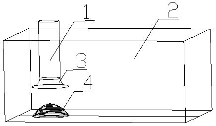
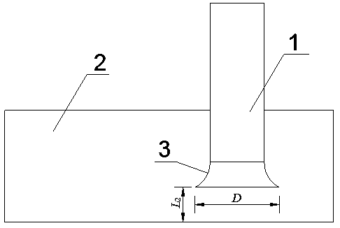
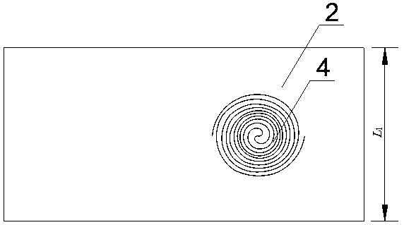
[0023] The present invention will be further described below in conjunction with the accompanying drawings and description of the accompanying drawings. In the figure, L 1 is the width of the inlet structure 2, D Be the trumpet mouth diameter of horn pipe 3, L 2 is the suspension height of the trumpet tube 3;

[0024] A water inlet structure vortex control device based on Fermat's spiral, comprising a vortex control device 4 arranged in the water inlet structure 2, a water suction pipe 1 and a trumpet pipe 3 connected with the water suction pipe 1 are arranged on the vortex control device 4, and The trumpet tube 3 is placed in the water inlet structure 2; when the vortex control device 4 is made, the following steps are included:

[0025] Step 1), take the width of the water inlet structure 2 L 1 and the horn mouth diameter of the horn tube 3 D As a constraint condition, the Fermat spiral equation is used to design the vortex control device, and the projection point of...


PUM


Abstract

The invention relates to a water inlet structure vortex control device based on the fermat's spiral. Manufacturing includes the following steps that firstly, the width L1 of a water inlet structure and the diameter D of the opening of a flare tube serve as constraint conditions, and a fermat's spiral equation is used for design; according to the width L1 of the water inlet structure and the diameter D of the opening of the flare tube, the fermat's spiral is drawn into a planar curve after the specific value of a is determined; secondly, according to the suspension height L2 of the flare tube and the number m of gaps of adjacent spirals in a plane, the vertical distance L3 between the two adjacent spirals is determined; thirdly, the planar curve is processed and manufactured through steel ribs in the same proportion, the surfaces of the steel ribs are coated with anti-rust paint after manufacturing, vertical stretching distribution is conducted according to the vertical distance L3, andthe three-dimensional vortex control device is obtained. The vortex control device is fixed to a bottom plate of the water inlet structure, and the center of the vortex control device and the centerof the opening of the flare tube are located in the same vertical line. By means of the device, energy concentration of bottom-attached vortexes can be effectively damaged, and the source of generation of the bottom-attached vortexes can be eliminated.

Description

technical field [0001] The invention relates to a Fermat spiral-based vortex control device for a water inlet structure, which belongs to the technical field of pumping station engineering. Background technique [0002] Small and medium-sized irrigation and drainage pumping stations often use a wet room pump room. The water inlet structure of this pump room mostly adopts a box culvert type water inlet structure or an open water inlet pool. of structures. For axial flow pumps and guide vane mixed flow pumps, the bell pipe and suction pipe are the transition sections between the water inlet structure and the inlet of the impeller chamber, and the internal flow state of the bell pipe and water suction pipe must be affected by the internal flow state of the water inlet structure. The main function of the water inlet structure is to provide good water inlet conditions for the pump inlet. If the flow velocity distribution inside the water inlet structure is uneven, or even vorte...

Claims


Application Information

Patent Timeline
Patent Type & Authority Applications(China)
IPC IPC(8): E03B5/02E03F5/22
CPCE03B5/02E03F5/22
Inventor 杨帆高慧刘超罗秀娜张海军孙丹丹
Owner YANGZHOU UNIV
Why Eureka
Try Eureka