
Automatic hydraulic elevator device

An elevator and hydraulic technology, which is applied in the direction of drilling equipment, earthwork drilling, drilling pipes, etc., can solve the problems of technical manual participation, low degree of automation, and low work efficiency, so as to improve workover efficiency, save labor, save cost effect

Pending Publication Date: 2018-04-20
SENIOR AI EQUIP CO LTD
View PDF0 Cites 1 Cited by
  • Summary
  • Abstract
  • Description
  • Claims
  • Application Information

AI Technical Summary

Problems solved by technology

Most of the existing elevators are manually opened and closed, with low degree of automation, low work efficiency, more technical and manual participation, poor working environment, and potential safety hazards

Method used


Image

  • Automatic hydraulic elevator device
  • Automatic hydraulic elevator device
  • Automatic hydraulic elevator device

Examples


Embodiment Construction

[0015] The present invention will be specifically described below in conjunction with the accompanying drawings and embodiments.

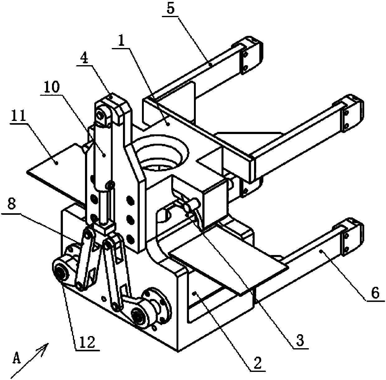
[0016] figure 1 Shown is the structural representation of the present invention.

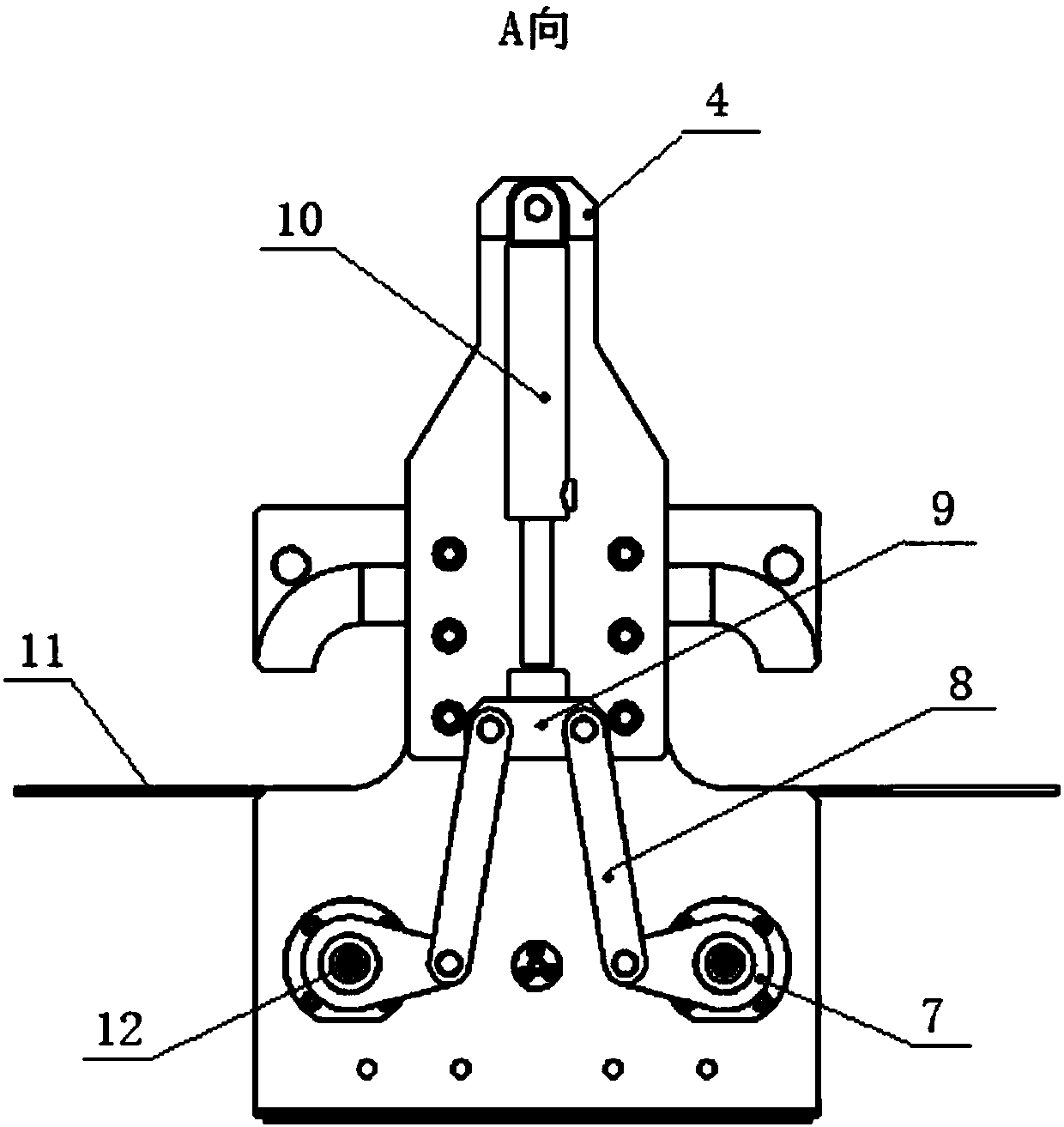
[0017] The present invention includes an elevator main body 1 , a swing seat 2 , a clamping sleeve 3 , a connecting plate 4 , an upper support frame 5 , a lower support frame 6 and a hydraulic cylinder 10 .

[0018] The middle part of the elevator main body 1 is provided with a cavity, and the two swing seats 2 are connected in the cavity of the elevator main body 1 through the swing seat shaft 12. The shaft 12 rotates; the two clamping sleeves 3 are fixed on the swing seat 2 and can swing with the swing seat 2.

[0019] The upper support frame 5 and the lower support frame 6 are installed on one end of the elevator main body 1, and the other end of the elevator main body 1 is equipped with a connecting plate 4.

[0020] The hydraulic cylinder 10 is fixed on the c...


PUM


Abstract

The invention discloses an automatic hydraulic elevator device. The automatic hydraulic elevator device comprises an elevator main body, two swing seats, two clamping sleeves, a connecting plate, an upper supporting frame, a lower supporting frame and a hydraulic cylinder. A cavity is formed in the middle of the elevator main body; the two swing seats are connected in the cavity of the elevator main body through swing seat shafts; the swing seats and the swing seat shafts are positioned through flat keys, and the swing seats can rotate along with the swing seat shafts; the two clamping sleevesare fixed to the swing seats and can swing along with the swing seats; the upper supporting frame and the lower supporting frame are mounted at one end of the elevator main body, and the connecting plate is mounted at the other end of the elevator main body; the hydraulic cylinder is fixed to the connecting plate, and a hydraulic rod of the hydraulic cylinder is connected with a connecting rod mechanism; the end of the connecting rod mechanism is connected with the swing seat shafts through keys, and the hydraulic cylinder drives the connecting rod mechanism to rotate; and opening and closingof the clamping sleeves are driven through the swing seat shafts. The automatic hydraulic elevator device has the beneficial effects that automatic elevating of an oil pipe is achieved, so that laborforce is saved, the well repairing efficiency is improved, the cost is saved, and automation of an oil pipe elevator is achieved.

Description

technical field [0001] The invention relates to an elevator device, which belongs to the technical field of oil field workover operation equipment. Background technique [0002] Elevators are tools used to lift drill pipes, casings and drill collars in drilling and workover tripping operations, and are indispensable tools in workover operations. Most of the existing elevators are manually opened and closed, with low degree of automation, low work efficiency, more technical and manual participation, poor working environment, and potential safety hazards. Contents of the invention [0003] The technical problem to be solved by the present invention is to provide an automatic hydraulic elevator device with a degree of automation aiming at the defects existing in the prior art. [0004] In order to solve this technical problem, the present invention provides an automatic hydraulic elevator device, which includes an elevator main body, a swing seat, a clamping sleeve, a connec...

Claims


Application Information

Patent Timeline
Patent Type & Authority Applications(China)
IPC IPC(8): E21B19/06
CPCE21B19/06
Inventor 谢俊飞孙汉军崔译戈李汝强孙宝京尹锐马卫立杨伟华张礼星
Owner SENIOR AI EQUIP CO LTD
Learn More