
Piston-piston pin-connecting rod combined unit matched structure

A connecting rod combination and matching structure technology, applied to pistons, engine components, machines/engines, etc., to achieve the effects of prolonging service life, preventing friction and wear, and avoiding jamming

Active Publication Date: 2018-04-20
CHINA NORTH ENGINE INST TIANJIN
View PDF5 Cites 3 Cited by
  • Summary
  • Abstract
  • Description
  • Claims
  • Application Information

AI Technical Summary

Problems solved by technology

[0004] In view of this, the present invention aims to propose a piston-piston pin-connecting rod combination unit matching structure to solve the matching problem between the piston-piston pin-connecting rod combination structure in the prior art

Method used

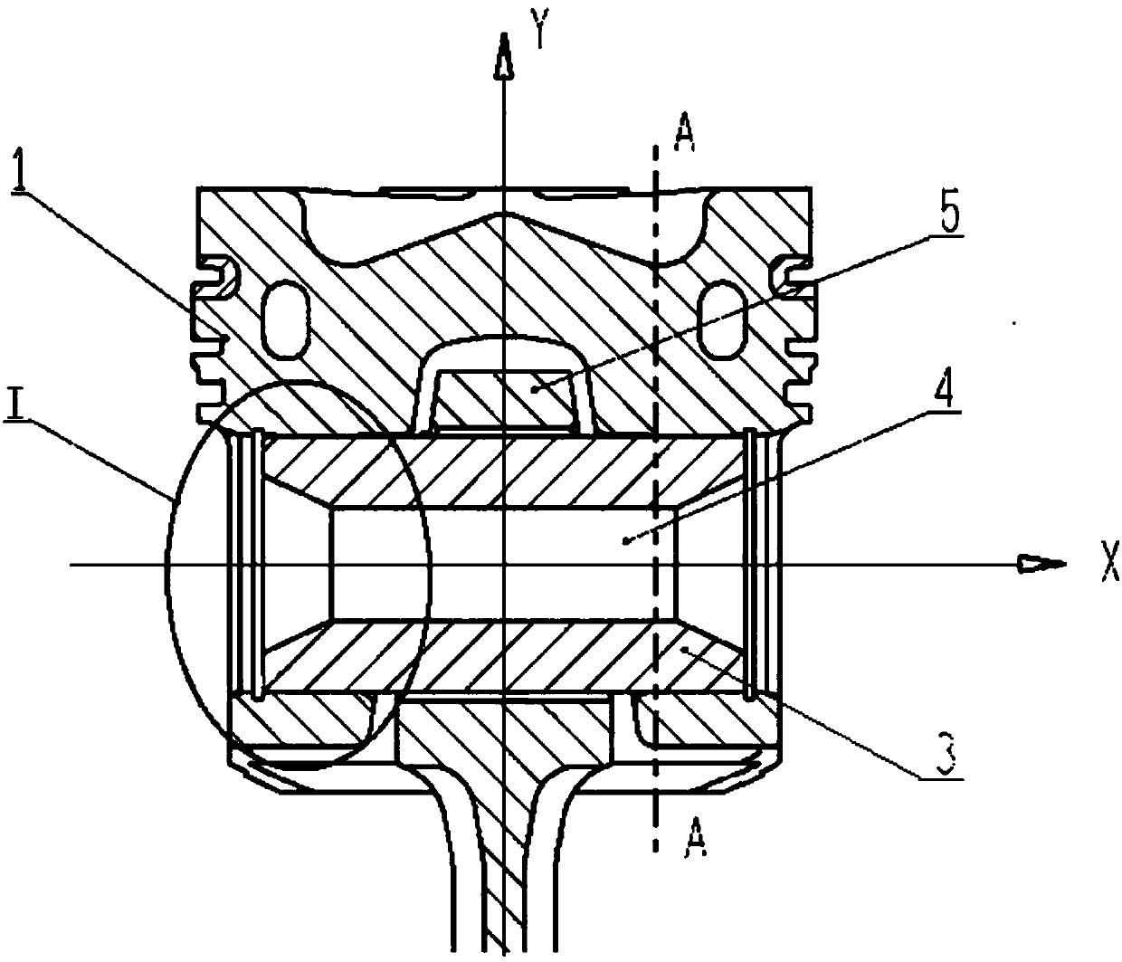
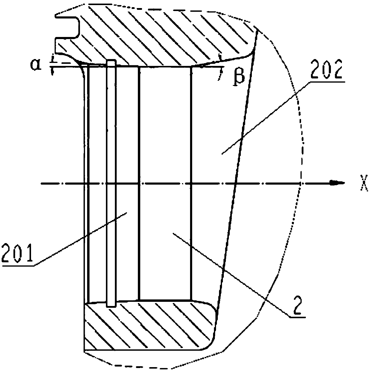
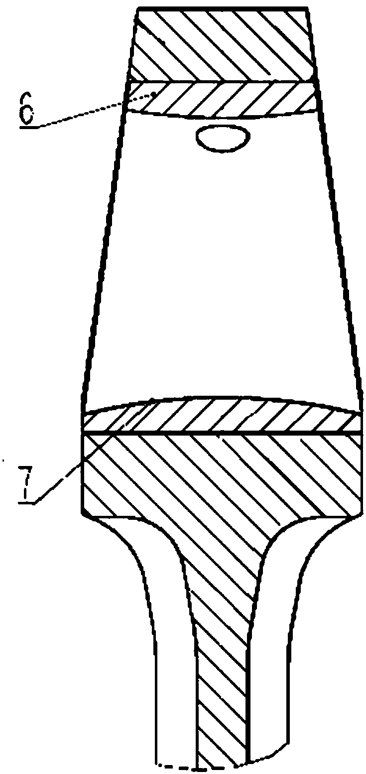

Image

  • Piston-piston pin-connecting rod combined unit matched structure
  • Piston-piston pin-connecting rod combined unit matched structure
  • Piston-piston pin-connecting rod combined unit matched structure

Examples


Embodiment Construction

[0025] It should be noted that, in the case of no conflict, the embodiments of the present invention and the features in the embodiments can be combined with each other.

[0026] In describing the present invention, it should be understood that the terms "center", "longitudinal", "transverse", "upper", "lower", "front", "rear", "left", "right", " The orientations or positional relationships indicated by "vertical", "horizontal", "top", "bottom", "inner" and "outer" are based on the orientations or positional relationships shown in the drawings, and are only for the convenience of describing the present invention and Simplified descriptions, rather than indicating or implying that the device or element referred to must have a particular orientation, be constructed and operate in a particular orientation, and thus should not be construed as limiting the invention. In addition, the terms "first", "second", etc. are used for descriptive purposes only, and should not be understood ...


PUM


Abstract

The invention provides a piston-piston pin-connecting rod combined unit matched structure comprising a piston, a connecting small head and a piston pin. A through pin seat hole is formed in the pistonand comprises two parts which are symmetrical with respect of the connecting rod small head, each part sequentially comprises an inner hole section, a middle hole section and an outer hole section from inside to outside, and the middle hole section is a straight hole. The two ends of the middle hole section are connected with the end, with a smaller diameter, of the inner hole section and the end, with a smaller diameter, of the outer hole section correspondingly. The connecting rod small head is located at one end of a connecting rod, and a connecting rod small head hole is formed in the connecting rod small head and extends into the piston. The piston pin penetrates through the pin seat hole and the connecting rod small head hole enable the connecting rod small head and the piston to behinged. According to the piston-piston pin-connecting rod combined unit matched structure, by improving the molded line structure of the pin seat hole, mechanical stress borne by the piston in work is effectively reduced, and thus the service life of the piston is prolonged. By increasing the ovality of the pin seat hole perpendicular to the longitudinal axis of the piston, the phenomenon of jamming of the piston pin in the pin seat hole can be effectively avoided.

Description

technical field [0001] The invention belongs to the technical field of engines, and in particular relates to a piston-piston pin-connecting rod combination structure. Background technique [0002] The piston-piston pin-connecting rod composite structure is a key power component for converting heat energy into kinetic energy, and this component bears a large mechanical load and thermal load. According to general knowledge, the gas pressure acting on the top of the piston is transmitted to the piston pin through the piston pin seat, and then transmitted to the small end of the connecting rod by the piston pin. Affected by the gas pressure, the piston pin has rotation and periodicity in the small end of the connecting rod. Therefore, the piston pin seat will also bear tensile, compressive and bending stresses on the horizontal and vertical planes. In addition, when the piston is subjected to a large thermal load, the piston will undergo a large thermal deformation, resulting i...

Claims


Application Information

Patent Timeline
Patent Type & Authority Applications(China)
IPC IPC(8): F02B75/32F02F3/00
CPCF02B75/32F02F3/00
Inventor 张利敏王延荣熊毕伟刘玉婷宋现浩赵志强冯云鹏杨雨
Owner CHINA NORTH ENGINE INST TIANJIN
Learn More