Large-flow gradual type gapless automatic limiting pilot valve for hydraulic device

A hydraulic device and automatic limit technology, applied in the field of hydraulic devices, can solve the problems of few functions, time-consuming and laborious operation, low pressure, etc., and achieve the effects of easy and labor-saving operation, good functional diversity and energy saving.

Inactive Publication Date: 2018-04-20
GUIZHOU FENGYANG HYDRAULIC
View PDF0 Cites 0 Cited by
  • Summary
  • Abstract
  • Description
  • Claims
  • Application Information

AI Technical Summary

Problems solved by technology

However, with the development of industrial technology, pilot valves that can only provide small flow rates, small optional ranges, few functions, and time-consuming and laborious operations can no longer meet the requirements of current industrial technology for pilot valves. Most of the pilot valves are water valves with low pressure and low flow rate, and there are relatively few pilot valves suitable for hydraulic systems widely used in industry.

Method used


Image

  • Large-flow gradual type gapless automatic limiting pilot valve for hydraulic device
  • Large-flow gradual type gapless automatic limiting pilot valve for hydraulic device
  • Large-flow gradual type gapless automatic limiting pilot valve for hydraulic device

Examples


Embodiment 1

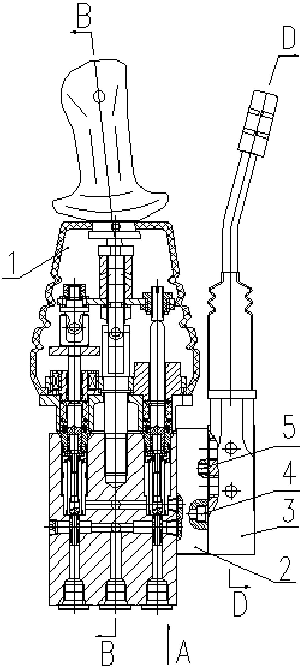
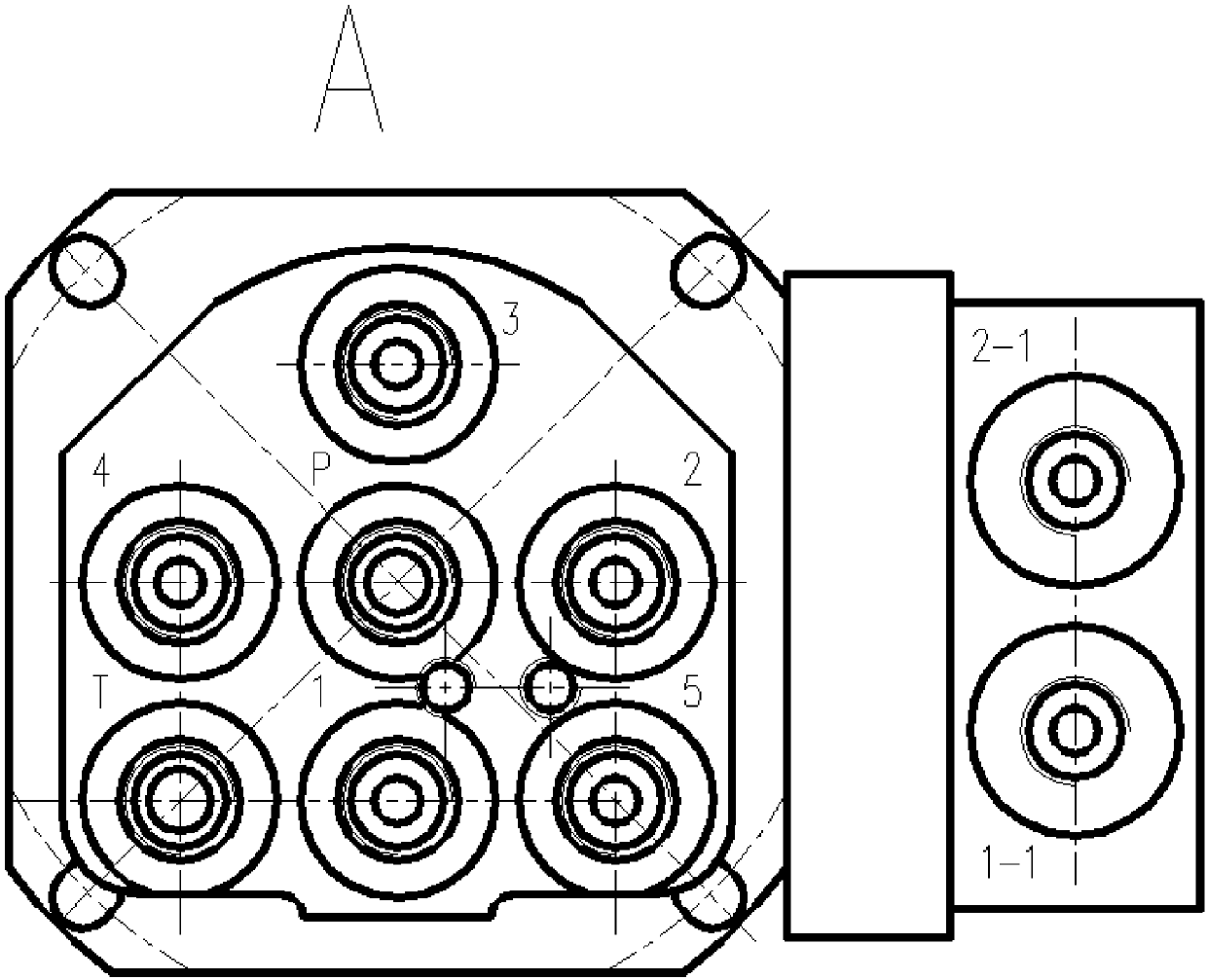
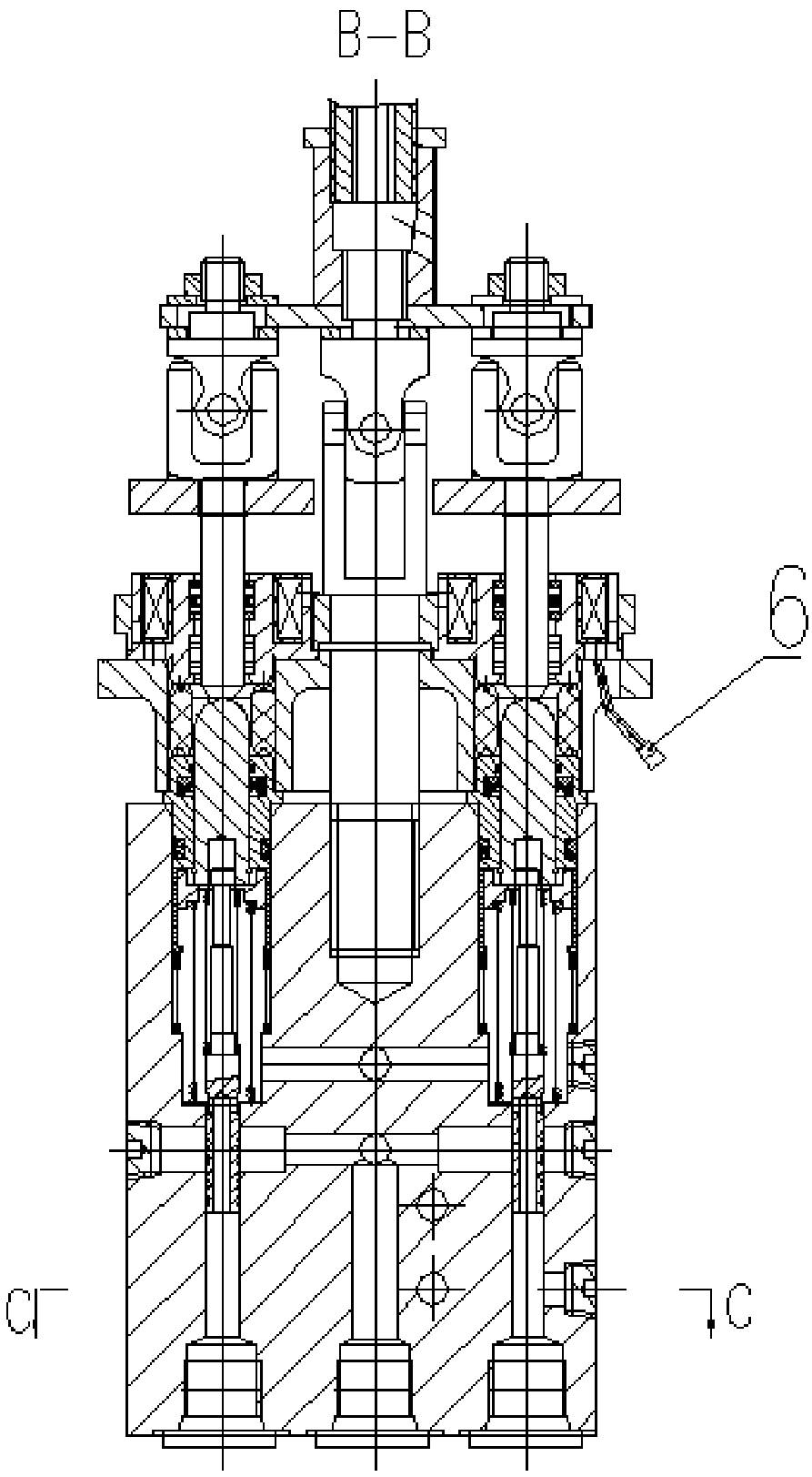
[0023] A large-flow progressive gapless automatic limit pilot valve for hydraulic devices. The pilot valve is composed of three parts: No. 1 valve 1, connecting plate 2, and No. 2 valve 3. The connecting plate 2 connects with The No. 1 valve 1 is connected, the No. 2 valve 3 is connected with the connection plate 2 through the second screw 5, and the No. 1 valve 1 is also equipped with an electromagnetic interface 6; the bottom of the No. 1 valve 1 is distributed with 7 oil passage interfaces in the shape of "you" , where the middle of the word "you" is the oil inlet port P, the left side of the bottom is the stop port T port, and the right side of the bottom is the additional stop port 5 port. The electromagnetic interface 6 in the No. 1 valve is connected to the built-in valve mechanism of the No. 1 valve; The bottom of No. 3 valve 3 is provided with two holes whose circle centers are parallel to ports 1-1 and 1-2 on the matching surface of connecting plate 2 and No. 2 valve ...

Embodiment 2

[0025] The whole is consistent with Example 1, the difference is:

[0026] Wherein the tightening torque of the first screw 4 is 12Nm; the tightening torque of the second screw 5 is 31Nm.

[0027] When using this embodiment, compared with Embodiment 1, the stability of the present invention will be slightly reduced, but it is still significantly better than the prior art.

Embodiment 3

[0029] The whole is consistent with Example 1, the difference is:

[0030] The tightening torque of the first screw 4 is 16Nm; the tightening torque of the second screw 5 is 39Nm.

[0031] When this embodiment is used, compared with Embodiment 1, the service life of the present invention will be slightly reduced, but it is still significantly better than the prior art.


PUM


Abstract

The invention relates to a large-flow progressive gap-free automatic position-limiting pilot valve for a hydraulic device, which consists of three parts: a No. 1 valve, a connecting plate, and a No. 2 valve; The electromagnetic interface in the No. 1 valve is connected to the built-in valve mechanism of the No. 1 valve; the bottom of the No. 2 valve is provided with 1‑1 port and 1‑2 port, the middle part is provided with two oil circuit ports, and the upper part is provided with a The rotary device that is connected to the shutter mechanism built into the No. 2 valve. The invention has the following advantages: 1. Progressive, sensitive operation; 2. Precise control without gaps; 3. Small operating force on the handle; 4. Electromagnetic end position locking can be realized at each control oil port, which can be controlled by the switch on the main machine Release the electromagnetic lock; 5. The fifth hydraulic control oil port can be used for additional functions; 6. When the operating handle is close to the end position, you can feel the resistance point.

Description

technical field [0001] The invention relates to the field of hydraulic devices, in particular to a large-flow progressive gapless automatic limit pilot valve for hydraulic devices. Background technique [0002] The pilot valve is an auxiliary valve used to manipulate the control mechanism in other valves or components. The conventional pilot valve has the following characteristics: 1) It forms a pilot control liquid bridge with a fixed liquid resistance, and controls the main valve, secondary valve or variable lever according to the input signal; 2) The flow rate of the first pilot valve is generally only 1 liter / min or so, maximum 3 liters / min. The flow rate of the secondary pilot valve should be determined according to the actual needs; 3) The input signal is relatively small; 4) It can accept a variety of input methods, such as manual, electric, hydraulic, pneumatic, mechanical cam, electric proportional, etc.; 5) In variable For pump control and other situations, a va...

Claims


Application Information

Patent Timeline
Patent Type & Authority Applications(China)
IPC IPC(8): F15B13/02
CPCF15B13/021
Inventor 刘建宇
Owner GUIZHOU FENGYANG HYDRAULIC
Why Eureka
Try Eureka