

Sealing ball valve
A technology for sealing ball valves and sealing rings, applied in the field of sealing ball valves, can solve problems such as ball valve leakage, achieve the effects of enhancing the sealing effect, improving the sealing effect, and prolonging the service life
- Summary
- Abstract
- Description
- Claims
- Application Information
AI Technical Summary
Problems solved by technology
Method used
Image

Examples
Embodiment Construction
[0030] The embodiments of the present invention will be described in detail below with reference to the accompanying drawings, but the present invention can be implemented in many different ways defined and covered by the claims.
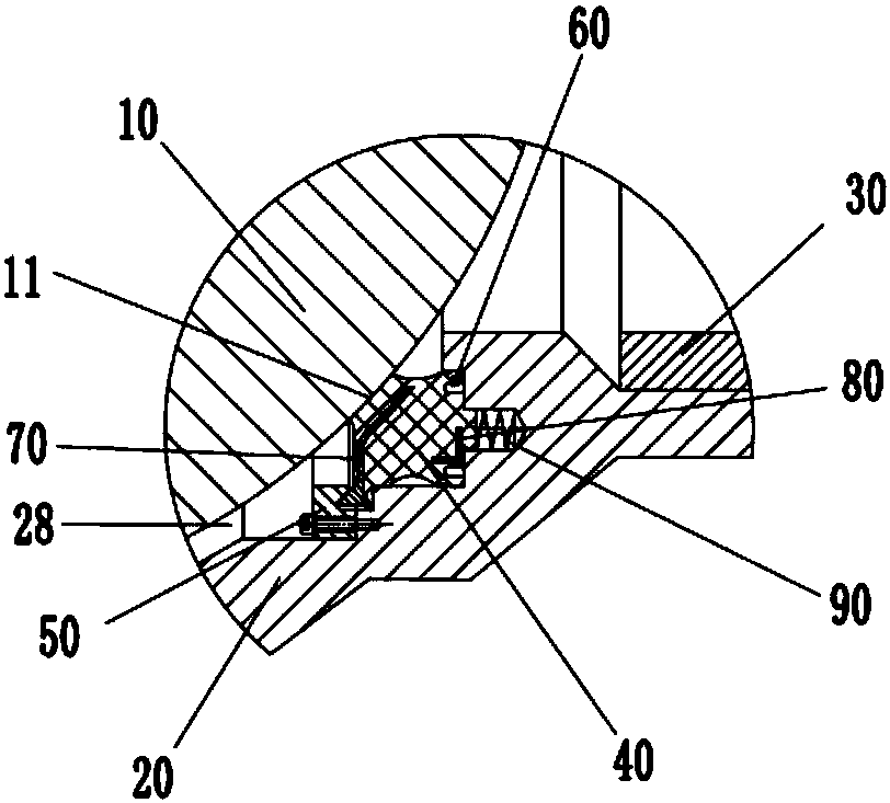
[0031] Refer below Figure 1 to Figure 7 The present invention is further described, as figure 1 A sealing ball valve shown includes a valve body 20 and a valve core ball 10. The right end of the valve body 20 is provided with a fourth hole 27, the second connecting pipe 30 is connected to the fourth hole 27, and the valve core ball 10 is arranged on the valve body. In the valve cavity 28 of the body 20, the sealed ball valve also includes a sealing ring 40 and a compression ring 50, the sealing ring 40 is arranged between the valve core ball 10 and the valve body 20, and the compression ring 50 is arranged in the first hole of the valve body 20 21 and is pressed against the flange 70c of the first frame 70 of the sealing ring 40, the above-mention...
PUM
 Abstract
Description
Claims
Application Information