
Continuous distributed optical fiber temperature monitoring system

A distributed optical fiber and monitoring system technology, applied in the field of temperature measurement, can solve the problems of high temperature point distance and temperature measurement accuracy, difficulty in determining over-limit points, and complicated lines, so as to achieve more temperature measurement points, reduce external interference, and reduce line complex effects

Pending Publication Date: 2018-04-20
沈春潇
View PDF1 Cites 2 Cited by
  • Summary
  • Abstract
  • Description
  • Claims
  • Application Information

AI Technical Summary

Problems solved by technology

[0006] At present, fire monitoring in large or important places still uses point-type temperature measurement sensors, which have many points, low precision, complex circuits, and are susceptible to interference, and it is difficult to determine the over-limit point
Although Rayleigh scattering and Raman scattering distributed optical fiber sensing technology is used to measure temperature, it is not as high as the temperature point distance and temperature measurement accuracy of continuous distributed Brillouin optical fiber temperature measurement system

Method used


Image

  • Continuous distributed optical fiber temperature monitoring system
  • Continuous distributed optical fiber temperature monitoring system
  • Continuous distributed optical fiber temperature monitoring system

Examples


Embodiment Construction

[0036] The present invention will be described in detail below in conjunction with the accompanying drawings, but it should be pointed out that the implementation of the present invention is not limited to the following embodiments.

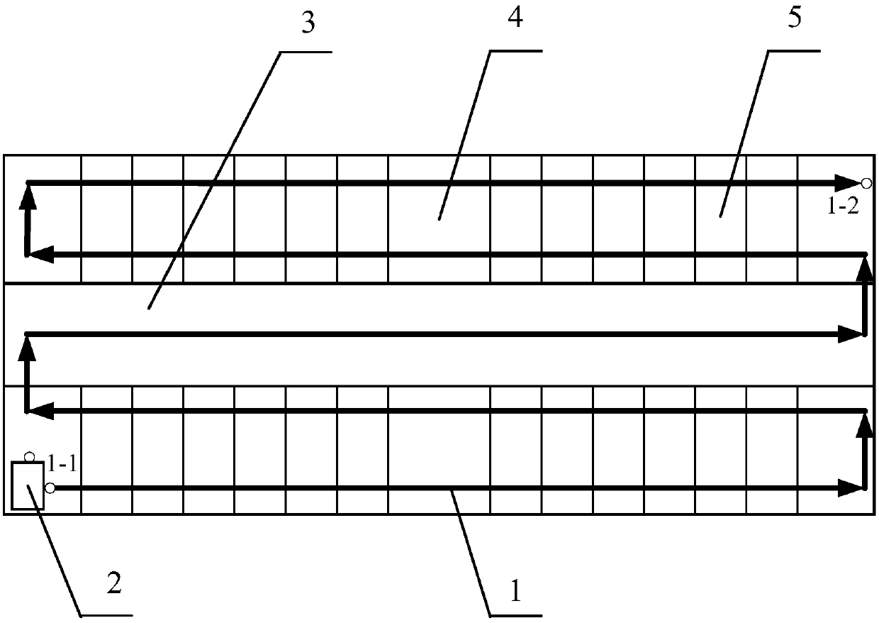
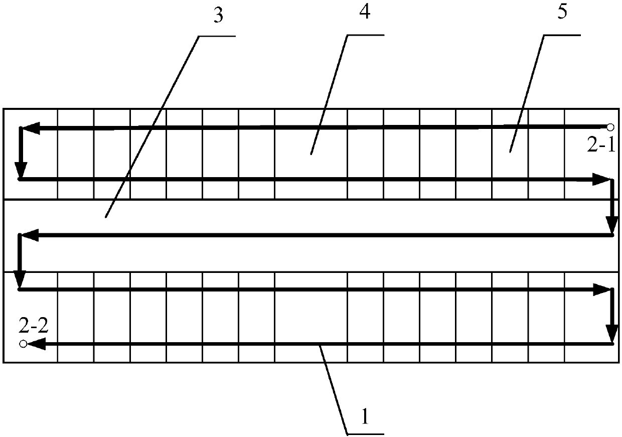
[0037] See figure 1 , Figure 7 , taking fiber optic monitoring of the temperature of a building as an example:

[0038] The continuous distributed optical fiber temperature monitoring system includes a temperature detector 2 and a temperature measuring optical fiber 1. The temperature measuring optical fiber 1 is one piece, which is continuously arranged at all positions to be monitored. The temperature measuring optical fiber 1 is connected to the temperature detector 2; The detector 2 includes a controller, a signal generator, a fiber laser, a preamplifier, a lock-in amplifier, a data acquisition card, an all-solid-state computer, and a GPRS / LTE module; 1 One end is connected to the fiber laser, and the other end is connected to the preampli...


PUM


Abstract

The invention relates to a continuous distributed optical fiber temperature monitoring system, comprising a temperature detector, and a temperature measuring optical fiber continuously disposed at allpositions where the temperatures are going to be monitored, wherein the temperature measuring optical fiber is connected with the temperature detector; the temperature detector comprises a controller, a signal generator, an optical fiber laser, a preamplifier, a lock-in amplifier, a data acquisition card, an all-solid-state computer and a GPRS / LTE module; the controller is connected with the optical fiber laser and the signal generator, one end of the temperature measuring optical fiber is connected with the optical fiber laser, and the other end is connected with the preamplifier; the signalgenerator is connected with the lock-in amplifier; and the preamplifier, the lock-in amplifier, the data acquisition card and the all-solid-state computer are connected in sequence. The advantages are: continuous temperature measurement of an entire large place is completed using a temperature measuring optical fiber; the signal generator and the amplifier of the temperature detector realize theaccuracy of temperature measurement, and the distance resolution of the temperature measuring point of the temperature measuring optical fiber can reach 2 cm.

Description

technical field [0001] The invention relates to the field of temperature measurement, in particular to a continuous distributed optical fiber temperature monitoring system used for fire fighting in large places. Background technique [0002] The fire department clearly stipulates that large or important places should be equipped with automatic fire monitoring and alarm systems. Such as: large and medium-sized computer rooms, warehouses for special valuables, libraries with 1 million volumes, important archives, cultural relics collection warehouses, with a total construction area of ​​more than 6000m2 2 shops, exhibition buildings, financial and financial buildings, large airports, large transmission and transformation substations, large passenger and freight stations, special and first-class theaters, hospitals, nursing homes and other places. [0003] Information technology and sensing technology represented by optical fiber communication and optical fiber sensing technol...

Claims


Application Information

Patent Timeline
Patent Type & Authority Applications(China)
IPC IPC(8): G01K11/32G01K11/322
CPCG01K11/32G01K11/322
Inventor 沈春潇王春岩
Owner 沈春潇
Learn More