
Transverse piezoelectric driving deformation mirror and the assembling method thereof

A technology of piezoelectric drive and piezoelectric drive, which is applied in the direction of optical components, optics, instruments, etc., can solve the problems of reducing the stability of the mirror surface and resonance frequency, prone to print-through effect, and the influence of the shape change of the mirror surface. Simple and convenient, reducing support stiffness and increasing deformation

Inactive Publication Date: 2018-04-20
NAT UNIV OF DEFENSE TECH
View PDF2 Cites 7 Cited by
  • Summary
  • Abstract
  • Description
  • Claims
  • Application Information

AI Technical Summary

Problems solved by technology

The "L"-shaped four-point support reduces the stability and resonance frequency of the mirror; although the fixed support of multi-cylindrical electrodes and non-electrode areas increases the amount of deformation, it has an impact on the surface shape of the mirror and is prone to print-through effects

Method used


Image

  • Transverse piezoelectric driving deformation mirror and the assembling method thereof
  • Transverse piezoelectric driving deformation mirror and the assembling method thereof

Examples


Embodiment Construction

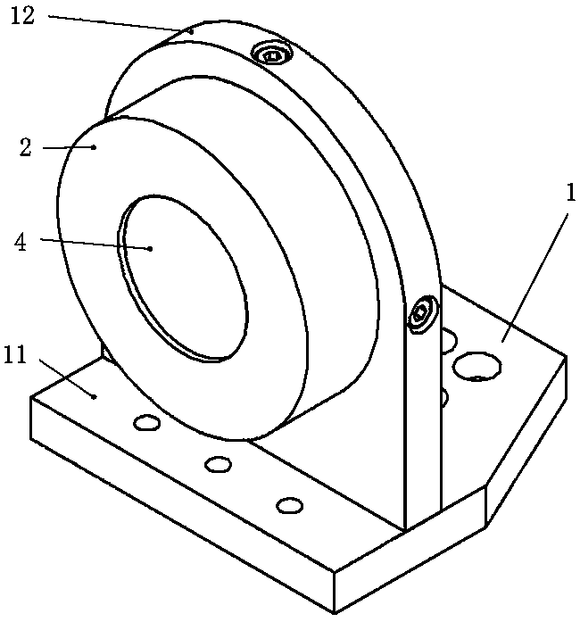
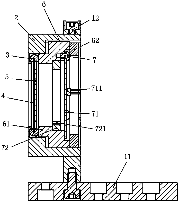
[0027] The present invention will be further described in detail below in conjunction with the accompanying drawings and specific embodiments.

[0028] Such as figure 1 with figure 2 As shown, the transverse piezoelectrically driven deformable mirror of this embodiment includes a base 1, a transverse shell 2, an elastic washer 3, a mirror 4, a piezoelectric driver 5, a pressing device 6 and an electrical connection assembly 7, and the transverse shell 2 Installed laterally on the base 1, the reflector 4 and the piezoelectric driver 5 are bonded and fitted in the inner hole of the lateral shell 2, the elastic washer 3 is installed on the edge of the reflector 4, and one end surface of the elastic washer 3 is movable with the transverse shell 2 Contact, the pressure applying device 6 is screwed into the inner hole of the transverse shell 2, and the pressure applying device 6 is in movable contact with the elastic washer 3, and the electrical connection assembly 7 is installed ...


PUM


Abstract

The invention discloses a transverse piezoelectric driving deformation mirror and an assembling method thereof. A transverse shell in the deformation mirror is arranged on a base, a reflecting mirrorand a piezoelectric actuator are bonded and arranged in the inner hole of the transverse shell in a sleeved mode, and an elastic gasket is arranged on the edge of the reflecting mirror. One end face of the elastic gasket is in movable contact with the transverse shell, and the pressure applying device is in threaded sleeve with the inner hole of the transverse shell, and is in contact with the elastic gasket; and an electricity receiving assembly is arranged on the pressure applying device and is connected with the piezoelectric actuator. The method comprises the following steps of s1, bondinga piezoelectric actuator with a reflector; s2 clamping and fastening on the side surface of the reflecting mirror and the upper surface and the lower surface of the edge by using an elastic gasket clamping sleeve, and arranging on a pressure applying device; s3, fixing the pressure applying device in the transverse shell sleeve and applying pressure to an elastic gasket; s4, welding a wire and the electricity receiving assembly together, and installing the electricity receiving assembly on the pressure applying device; s5, transversely fixing the transverse shell sleeve on the base. The device has the advantages of being simple in structure, convenient to manufacture and install and capable of effectively improving the deformation of each electrode.

Description

technical field [0001] The invention belongs to the field of wavefront correction of optical adaptive optics systems, and in particular relates to a transverse piezoelectric-driven deformable mirror and an assembly method thereof, which are used for correcting wavefront aberrations of optical systems such as lasers. Background technique [0002] The widely used transverse piezoelectric deformable mirror is the core device of the adaptive optics system. Its structure includes reflective mirror, bonding layer, piezoelectric ceramic sheet, supporting fixture and so on. These structures have a certain influence on the performance of the deformable mirror, and then affect the practicability of the adaptive system. The performance indicators of deformable mirrors mainly include deformation, resonance frequency, spatial aberration fitting accuracy, stability, etc. [0003] The clamping method of the deformable mirror has an influence on the influence function, the amount of defor...

Claims


Application Information

Patent Timeline
Patent Type & Authority Applications(China)
IPC IPC(8): G02B26/06
Inventor 铁贵鹏戴一帆关朝亮范占斌宁禹刘俊峰
Owner NAT UNIV OF DEFENSE TECH
Learn More