Supercharge Your Innovation With Domain-Expert AI Agents!

Dual-rotor structure voltage regulating device based on angular displacement control

A voltage regulating device and angular displacement technology, applied in the field of transformers, can solve the problems of deviation of output voltage from a preset value, adverse effects of external electrical equipment, inconvenient realization of transformers, etc., to achieve the effect of improving accuracy

Inactive Publication Date: 2018-04-20
SUZHOU KEAIJIA AUTOMATION TECH CO LTD
View PDF12 Cites 2 Cited by
  • Summary
  • Abstract
  • Description
  • Claims
  • Application Information

AI Technical Summary

Problems solved by technology

[0002] In low-voltage and ultra-low-voltage power transmission and transformation, transformers are irreplaceable devices. Although there are many types of existing transformers, most of them are designed as specific transformer structures. For some special fields, it is often necessary to adjust and transform the transformer , the general transformer cannot be realized conveniently. The motor is used to control the rotation of the rotor shaft to change the relative electrical angle of the stator and the rotor. The stator is the primary winding of the transformer, and the rotor is the secondary winding of the transformer, so as to continuously change the voltage. Output size, realize the ratio adjustment of input and output voltage
[0003] The disadvantage of the prior art structure is that the output voltage of the transformer needs to be changed by changing the rotation angle of the rotor shaft. For a transformer with this structure, the output voltage of the transformer is usually collected by the voltage collector and fed back to the controller. When the collected output voltage reaches the preset voltage, the rotor shaft will continue to rotate due to inertia until it stops rotating. At this point, the output voltage will deviate from the preset value and cause adverse effects on the use of external electrical equipment.

Method used


Image

  • Dual-rotor structure voltage regulating device based on angular displacement control
  • Dual-rotor structure voltage regulating device based on angular displacement control
  • Dual-rotor structure voltage regulating device based on angular displacement control

Examples


Embodiment Construction

[0041] The present invention will be further described in detail below in conjunction with the accompanying drawings, so that those skilled in the art can implement it with reference to the description.

[0042] It should be understood that terms such as "having", "comprising" and "including" as used herein do not entail the presence or addition of one or more other elements or combinations thereof.

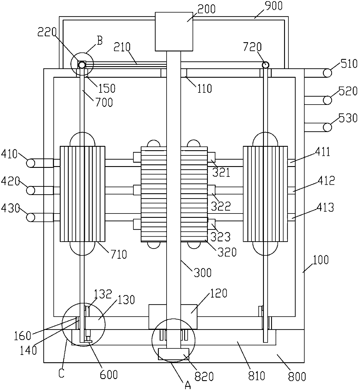
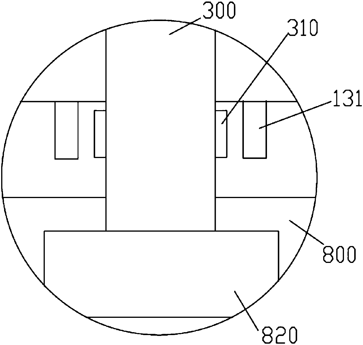
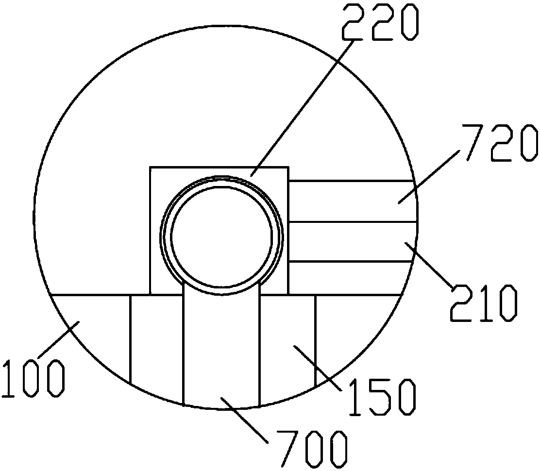
[0043] The present invention provides a dual-rotor structure pressure regulating device based on angular displacement control, such as Figure 1-9 As shown, the voltage regulating device includes a voltage regulating device body 100, a rotatable primary winding 170 and a rotatable secondary winding 320. Specifically, a rotatable barrel-shaped bracket 700 is longitudinally arranged on the outer periphery of the pressure regulating device body 100, The barrel-shaped bracket 700 is made of insulating material to avoid conduction with the main body of the voltage regulating device. ...


PUM


Abstract

The invention discloses a dual-rotor structure voltage regulating device based on angular displacement control. The dual-rotor structure voltage regulating device comprises a primary winding and a secondary winding which are arranged rotatably, wherein the primary winding is positioned on the periphery of the secondary winding, three conducting rings are arranged on the inner side wall of a voltage regulating device body at intervals, each conducting ring is conductively connected with a corresponding phase line of the primary winding respectively, a base is arranged at the lower end of the voltage regulating device body, the bottom of a rotor shaft is arranged at the center of the base rotatably, a groove is formed in the center of the upper end of the base, the inner diameter of the groove is not smaller than the outer diameter of a rotating base plate, a fixed gear is arranged on the periphery of the lower end of the rotor shaft, a clutch gear is arranged on the periphery of the fixed gear, and the rotor shaft is selectively linked with the rotating base plate; a first driving mechanism is connected with the clutch gear, a second driving mechanism is arranged at the upper end ofthe rotor shaft, and a third driving mechanism is connected with the primary winding rotatably, wherein the secondary winding is provided with a reading head and an angular displacement ball grid scale. The device solves the technical problem that the output voltage of the voltage regulating device is inaccurate.

Description

technical field [0001] The present invention relates to a transformer, more specifically, the present invention relates to a double-rotor structure voltage regulating device based on angular displacement control. Background technique [0002] In low-voltage and ultra-low-voltage power transmission and transformation, transformers are irreplaceable devices. Although there are many types of existing transformers, most of them are designed as specific transformation structures. For some special fields, it is often necessary to adjust and transform the transformer. , the general transformer cannot be realized conveniently. The motor is used to control the rotation of the rotor shaft to change the relative electrical angle of the stator and the rotor. The stator is the primary winding of the transformer, and the rotor is the secondary winding of the transformer, so as to continuously change the voltage. The output size realizes the ratio adjustment of the input and output voltage...

Claims


Application Information

Patent Timeline
IPC IPC(8): H01F29/12H01F27/40H01F27/29
CPCH01F29/12H01F27/29H01F27/402
Inventor 储建华高霞
Owner SUZHOU KEAIJIA AUTOMATION TECH CO LTD
Features
  • R&D
  • Intellectual Property
  • Life Sciences
  • Materials
  • Tech Scout
  • Unparalleled Data Quality
  • Higher Quality Content
  • 60% Fewer Hallucinations
Learn More