
Rotor structure and motor comprising same

A rotor structure, rotor shaft technology, applied in the magnetic circuit shape/style/structure, magnetic circuit rotating parts and other directions, can solve the problems of magnetic ring burst, low matching accuracy, uneven motor air gap, etc., to improve the coaxial degree, avoid bursting, and improve the effect of assembly accuracy

Pending Publication Date: 2018-04-20
ZHUHAI GREE REFRIGERATION TECH CENT OF ENERGY SAVING & ENVIRONMENTAL PROTECTION
View PDF0 Cites 0 Cited by
  • Summary
  • Abstract
  • Description
  • Claims
  • Application Information

AI Technical Summary

Problems solved by technology

[0004] 1. When a small gap is used between the magnetic ring and the rotor shaft, the magnetic ring may burst due to the expansion of the glue solidification;
[0005] 2. When a large gap is used between the magnetic ring and the rotor shaft, the coaxiality of the magnetic ring and the rotor shaft will be poor, and the matching accuracy will be low;
[0006] 3. When the coaxiality of the magnetic ring and the rotating shaft is poor, the air gap of the motor will be uneven, resulting in unilateral magnetic pull, which will affect the control accuracy of the motor

Method used


Image

  • Rotor structure and motor comprising same
  • Rotor structure and motor comprising same
  • Rotor structure and motor comprising same

Examples


Embodiment Construction

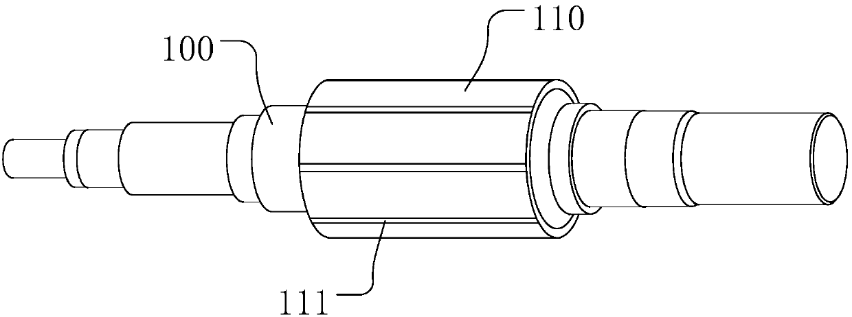
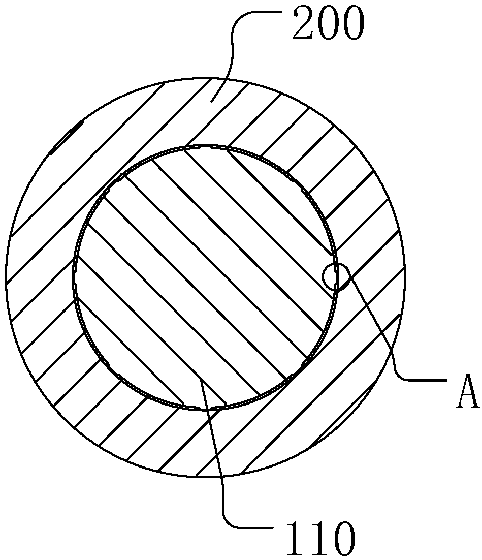
[0028] The present invention is described below based on examples, but the present invention is not limited to these examples. Those of ordinary skill in the art will appreciate that the drawings provided herein are for illustration purposes and are not necessarily drawn to scale.

[0029] Unless the context clearly requires, throughout the specification and claims, "comprises", "comprises" and similar words should be interpreted in an inclusive sense rather than an exclusive or exhaustive meaning; that is, "including but not limited to" meaning.

[0030] In the description of the present invention, it should be understood that the terms "first", "second" and so on are used for descriptive purposes only, and cannot be interpreted as indicating or implying relative importance. In addition, in the description of the present invention, unless otherwise specified, "plurality" means two or more.

[0031] Such as figure 1 , 2 As shown, the rotor structure provided by the present...


PUM


Abstract

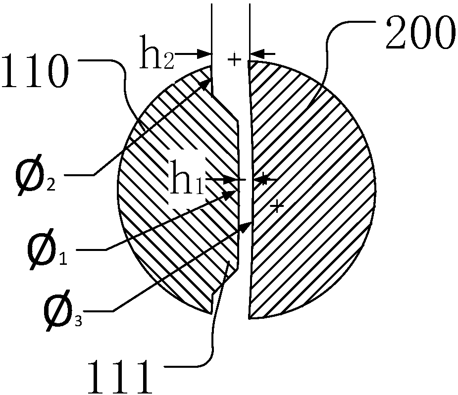
The invention discloses a rotor structure and a motor comprising the same. The rotor structure comprises a rotor shaft and a permanent magnet, the rotor shaft comprises a permanent magnet mounting part, the permanent magnet sleeves the permanent magnet mounting part and is bonded to the permanent magnet mounting part, a binding agent accommodating space is formed between the outer wall surface ofthe permanent magnet mounting part and the inner wall surface of the permanent magnet, matching structures are arranged on the outer wall surface of the permanent magnet mounting part and / or the innerwall surface of the permanent magnet, and the matching structures make the radial distance between the outer wall surface of the permanent magnet mounting part and the inner wall surface of the permanent magnet be inconstant. According to the invention, by arranging the matching structures on the permanent magnet mounting part of the rotor shaft and / or the inner wall of the permanent magnet, thedistance between the outer wall surface of the permanent magnet mounting part and the inner wall surface of the permanent magnet is variable. On the parts with larger distances, enough accommodating and expansion spaces are provided for the binding agent, and the permanent magnet is cracked due to adhesive expansion is avoided; on the parts with smaller distances, the permanent magnet cooperates with the permanent magnet mounting part, and the coaxiality of the permanent magnet and the permanent magnet mounting part can be improved.

Description

technical field [0001] The invention relates to the technical field related to motors, in particular to a rotor structure and a motor including the same. Background technique [0002] The rotor is an important part of the motor, and its precision level directly affects the performance of the motor. The servo motor has high control precision and good performance, so it requires higher precision of the rotor. [0003] The traditional surface-mount magnetic ring rotor structure uses glue to bond the circular rotor shaft and the magnetic ring together to prevent the permanent magnet from moving. However, this rotor shaft structure has the following disadvantages: [0004] 1. When a small gap is used between the magnetic ring and the rotor shaft, the magnetic ring may burst due to the expansion of the glue solidification; [0005] 2. When a large gap is used between the magnetic ring and the rotor shaft, the coaxiality of the magnetic ring and the rotor shaft is poor, and the ma...

Claims


Application Information

Patent Timeline
IPC IPC(8): H02K1/27H02K1/28
CPCH02K1/27H02K1/28
Inventor 张育州王瑞东黄侠昌李峰岩
Owner ZHUHAI GREE REFRIGERATION TECH CENT OF ENERGY SAVING & ENVIRONMENTAL PROTECTION
Learn More