Supercharge Your Innovation With Domain-Expert AI Agents!

Compressor

A compressor and compression mechanism technology, applied in the field of compressors, can solve problems such as difficult crankshaft analysis, difficult to reduce rotor noise, etc., and achieve the effect of simple structure

Active Publication Date: 2018-04-20
DAIKIN IND LTD
View PDF10 Cites 1 Cited by
  • Summary
  • Abstract
  • Description
  • Claims
  • Application Information

AI Technical Summary

Problems solved by technology

In such a compressor, since it is difficult to analyze the inclination and deflection of the crankshaft and take countermeasures, there is a problem that it is difficult to reduce the vibration in the radial direction of the rotor and the noise generated therefrom.

Method used


Image

  • Compressor
  • Compressor
  • Compressor

Examples


Embodiment Construction

[0032] Next, the compressor of the present invention will be described in more detail with reference to the illustrated embodiments.

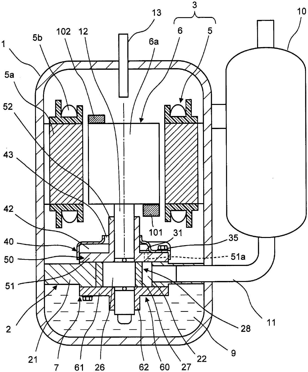
[0033] figure 1 A longitudinal sectional view of a compressor according to one embodiment of the present invention is shown.

[0034] like figure 1 As shown, the compressor according to the present embodiment includes: an airtight container 1; a compression mechanism part 2 disposed in the airtight container 1; The mechanism part 2 is driven. The compressor 1 of the present embodiment is a single-cylinder rotary compressor.

[0035] A compression mechanism unit 2 is arranged on the lower side in the airtight container 1 of the compressor, and a motor 3 is arranged on the upper side of the compression mechanism unit 2 . The motor 3 has a rotor 6 connected to the upper side of the rotary shaft 12 , and a permanent magnet (not shown) embedded in the rotor 6 , and a stator 5 surrounding the outer peripheral side of the rotor 6 . The compressio...


PUM


Abstract

This compressor is provided with a rotating shaft (12) having an eccentric part (26), an electric motor having a rotor (6) linked to the rotating shaft (12), a compression mechanism section driven bythe electric motor via the rotating shaft (12), a first balancing weight (101) provided to one end, in the axial direction, on the side of the rotor (6) that faces the compression mechanism section, and a second balancing weight (102) provided to the other end of the rotor (6) in the axial-direction. The first and second balancing weights (101, 102) are disposed so that the centers of gravity of the first and second balancing weights (101, 102) are positioned at pre-set advanced angles theta 1, theta 2 in the rotational direction of the rotor (6), relative to a reference plane passing throughthe rotational center O of the rotating shaft (12), along the eccentric direction of the eccentric part (26). A compressor is thereby provided in which vibration and noise of the rotor can be reducedinexpensively and with a simple configuration, without adding any new components.

Description

technical field [0001] The present invention relates to compressors. Background technique [0002] Conventionally, as a compressor, there is a structure in which a crankshaft having an eccentric portion is connected to a rotor of a motor, and the motor drives the compression mechanism through the crankshaft (for example, refer to Japanese Patent Application Laid-Open No. 2004-270654 (Patent Document 1)). [0003] prior art literature [0004] patent documents [0005] Patent Document 1: Japanese Patent Laid-Open No. 2004-270654 Contents of the invention [0006] The problem to be solved by the invention [0007] However, in the above-mentioned compressor, the crankshaft tilts in the bearing due to the compressive load applied to the crankshaft during operation, or the crankshaft occurs due to the compressive load, the load caused by the unevenness of the air gap of the motor, and the centrifugal force of the balance weight. In deflection, the rotor of the motor rotate...

Claims


Application Information

Patent Timeline
IPC IPC(8): F04B39/00F04C23/02
CPCF04B39/00F04C23/02F04C29/0057F04C18/356F04C2240/807F04C29/0021F04B39/0027F04C2240/40F04C2240/60F04C2240/809H02K7/04
Inventor 樋口顺英
Owner DAIKIN IND LTD
Features
  • R&D
  • Intellectual Property
  • Life Sciences
  • Materials
  • Tech Scout
  • Unparalleled Data Quality
  • Higher Quality Content
  • 60% Fewer Hallucinations
Learn More