Eureka AIR delivers breakthrough ideas for toughest innovation challenges, trusted by R&D personnel around the world.

Intelligent electronic mosquito swatter

An electric mosquito swatter, intelligent technology, applied to the device, application, animal husbandry, etc. to capture or kill insects, can solve the problems of poor user experience, inability to eliminate flies, and flies touched by the power grid, so as to achieve good user experience and good Eliminate mosquitoes, good effect

Inactive Publication Date: 2018-04-24
JIEYANG QIATAILI ELECTRONICAL APPLIANCE CO LTD
View PDF8 Cites 0 Cited by
  • Summary
  • Abstract
  • Description
  • Claims
  • Application Information

AI Technical Summary

Problems solved by technology

[0003] But in normal use, it is relatively useful for mosquitoes, but when used on flies, due to the sensitivity of flies, the power grid cannot touch the flies, causing the flies to fly away and unable to eliminate the flies, which leads to poor user experience. occur

Method used


Image

  • Intelligent electronic mosquito swatter
  • Intelligent electronic mosquito swatter
  • Intelligent electronic mosquito swatter

Examples


Embodiment 1

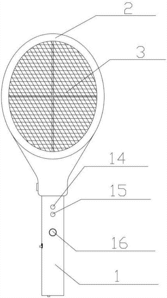
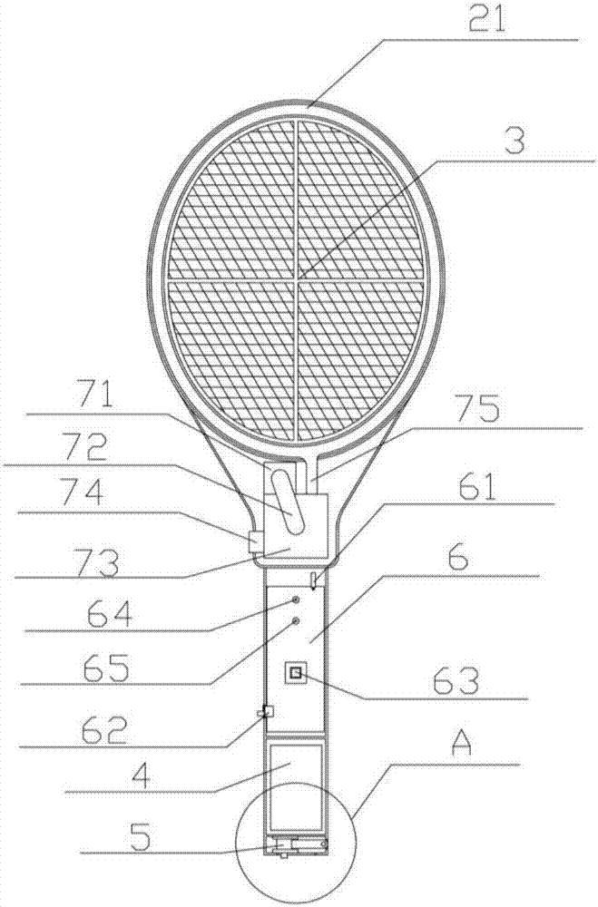
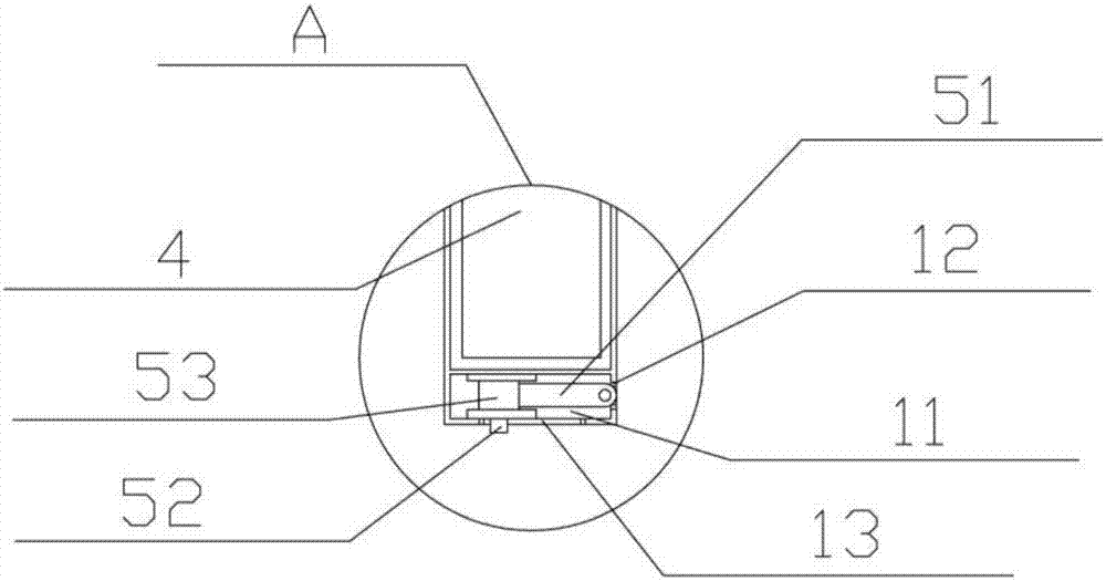
[0025] A kind of intelligent electric mosquito swatter of embodiment 1 of the present invention such as Figure 1-4 As shown, it includes a handle 1, a racket frame 2, a racket face 3, a battery 4, a charging connector 5 and a circuit board 6, the handle 1 is connected to the racket frame 2, and the racket face 3 is placed on the racket In the frame 2, the charging connector 5 is fixed under the handle 1, the battery 4 is fixed on the lower part of the handle 1 above the charging connector 5, and the circuit board 6 is fixed on the handle. The middle and upper part of the handle 1, the circuit board 6 is electrically connected with the battery 4, the charging connector 5 and the racket surface 3 respectively, and also includes an exhaust fan, an air duct 21 and a vibration switch 61, and the exhaust fan is installed At the position where the top of the handle 1 is close to the racket frame 2, the air duct 21 is arranged around the racket frame 2, and the air duct 21 is evenly ...

Embodiment 2

[0032] This embodiment is basically the same as Embodiment 1, the difference is that: the air duct 21 is formed integrally with the racket frame 2, this setting mainly reduces the installation of the air duct 21, and is directly manufactured together with the racket frame 2 through a process come out, the accuracy is higher, and the installation is more convenient at the same time, but relatively because it belongs to direct splicing, therefore, there will be a situation of low air tightness. Compared with the air duct 21 of Example 1, the air tightness is worse, but it is convenient Installation and mass production are more convenient.


PUM


Abstract

The invention discloses an intelligent electronic mosquito swatter which comprises a swatter handle, a swatter frame, a swatter face, a battery, a charging connector and a circuit board. The swatter handle is connected with the swatter frame, the swatter face is arranged in the swatter frame, the charging connector is fixed below the swatter handle, and the battery is fixed to the position, located above the charging connector, of the lower portion of the swatter handle. The circuit board is fixed to the upper middle portion of the swatter handle, the circuit board is electrically connected with the battery, the charging connector and the swatter face, and an exhaust fan, an air channel and a vibration switch are further included. According to the intelligent electronic mosquito swatter, the swatter face generates a negative pressure gas field through the exhaust fan, approaching mosquitoes and flies are attracted by negative pressure and cannot fly away from the swatter face, then themosquitoes can be killed effectively and better, meanwhile, the flies cannot fly out of the range of the swatter face, the mosquito and fly killing effect is better, and the user experience is better.

Description

technical field [0001] The invention belongs to the technical field of electronic mosquito killers, and in particular relates to an intelligent electric mosquito swatter. Background technique [0002] There are many mosquitoes in summer, and electric mosquito swatters, as an efficient and environmentally friendly mosquito killing tool, have increasingly entered every family. The electric mosquito swatter uses a boost circuit to generate a high-voltage direct current of 2500 to 3000 volts between the positive and negative power grids. When mosquitoes and other pests close to the power grid touch the power grid, the power grid will generate a short-circuit current to kill them. , good effect, no pollution and other advantages, welcomed by people. [0003] But in normal use, it is relatively useful for mosquitoes, but when used on flies, due to the sensitivity of flies, the power grid cannot touch the flies, causing the flies to fly away and unable to eliminate the flies, whic...

Claims


Application Information

Patent Timeline
Patent Type & Authority Applications(China)
IPC IPC(8): A01M3/02
CPCA01M3/02A01M3/025A01M2200/012
Inventor 林先纪建宏
Owner JIEYANG QIATAILI ELECTRONICAL APPLIANCE CO LTD
Why Eureka
Eureka Blog
Learn More