

Combined shaping anchor cushion plate and its manufacturing method
A technology of combined molding and manufacturing method, applied in the direction of structural elements, building components, building reinforcements, etc., can solve the problems affecting the performance of the anchor pad, and achieve the effects of strong practicability, improved product quality, and simple production process.
- Summary
- Abstract
- Description
- Claims
- Application Information
AI Technical Summary
Problems solved by technology
Method used
Image

Examples
Embodiment 1
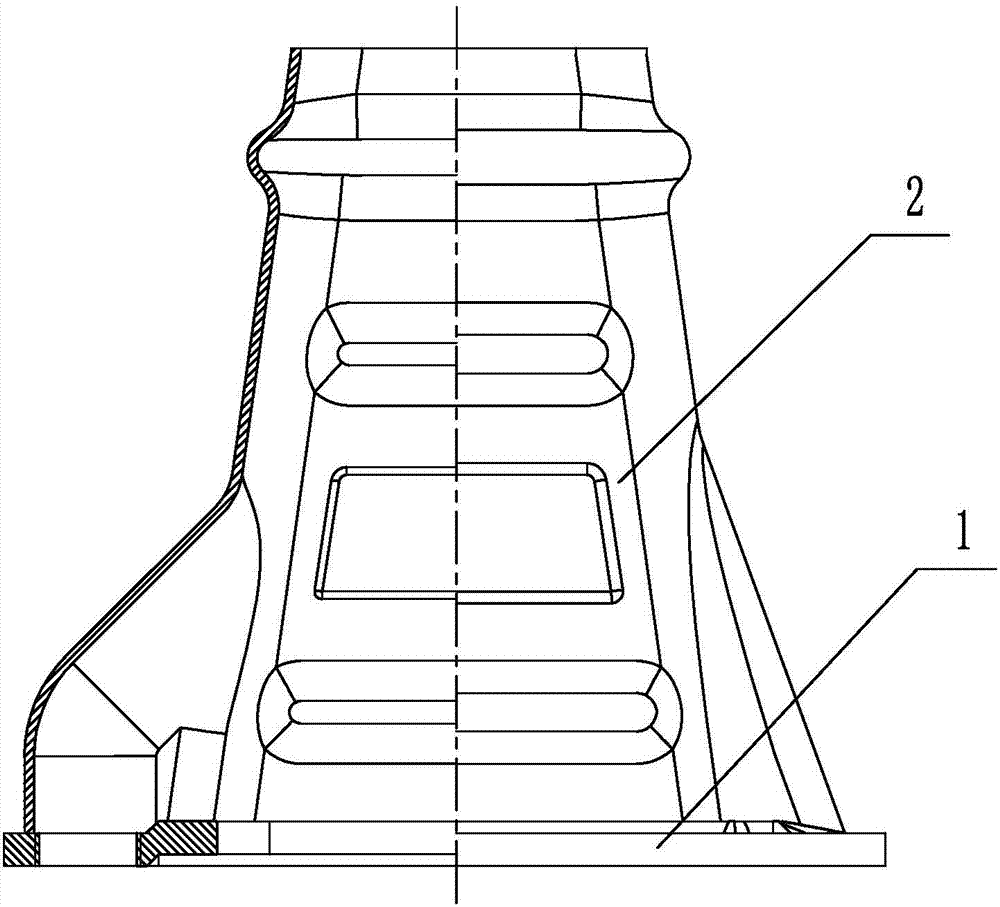
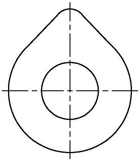
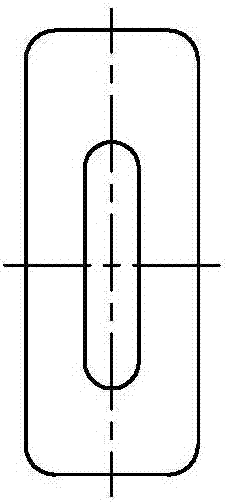
[0049] A composite shaped anchor pad, such as figure 1 As shown, the combined anchor backing plate includes a pressure backing plate 1 and a trumpet tube 2 of a separate structure, and the pressure backing plate is provided with an installation threaded hole 12 and a grouting hole 13, so as to facilitate construction installation and tunnel grouting; There is a notch 11 on the backing plate 1; the shape of the pressure-bearing backing plate is circular, oval, rectangular or square (see Figure 2-1 to Figure 2-3 ).
[0050] The trumpet tube 2 is formed by splicing two steel plates through welding, riveting or buckling and crimping;
[0051] In the state of use, the pressure-bearing backing plate 1 and the trumpet tube 2 of the separate structure are combined into the composite anchor backing plate by welding, riveting or crimping.
[0052]There are different implementations according to the form of the stopper 11 on the pressure-bearing backing plate 1 and the structure of th...
Embodiment 2
[0061] A method for making a combined anchor backing plate, that is, the method for making a combined anchor backing plate described in Embodiment 1. The method is to manufacture a pressure backing plate and a horn tube by punching or stretching respectively, and the horn tube consists of 2 to 6 pieces of steel plates are spliced together by welding, riveting or buckling and crimping, and then the integral trumpet tube and pressure-bearing backing plate are combined by welding, riveting or buckling and crimping to form a combined anchor backing plate; it Include the following steps:
[0062] A. Cutting material:
[0063] A1. According to the design of the pressure backing plate of the anchor backing plate, select a steel plate of appropriate size to punch or cut into the shape and size required for the pressure backing plate 1;
[0064] A2. According to the shape and size of the trumpet tube 2, the design is composed of 2 to 8 pieces that are stamped and formed respectively...
PUM
 Abstract
Description
Claims
Application Information