
Method, device and equipment controlling new energy power station active power

A technology of active power and new energy, applied in the direction of circuit devices, photovoltaic power generation, electrical components, etc., can solve the problems of new energy units that cannot realize rapid adjustment of active power, large errors, and slow recovery time

Active Publication Date: 2018-04-24
NR ELECTRIC CO LTD +1
View PDF6 Cites 8 Cited by
  • Summary
  • Abstract
  • Description
  • Claims
  • Application Information

AI Technical Summary

Problems solved by technology

[0002] New energy power generation technologies represented by wind power and photovoltaics have developed rapidly in recent years, and the proportion of new energy installed capacity in some areas has been quite high; due to the intermittent and fluctuating characteristics of new energy output, the safe and stable operation of the power system is facing great challenges. The power grid needs to fully exploit the regulation capacity to make up for the intermittency of new energy output, so as to ensure continuous and reliable power supply to the load; at present, at a specific moment, when the power grid operating parameters (frequency, voltage, etc.) are abnormal or fail, The active power adjustment method is mostly manual adjustment. Due to the manual adjustment, there are problems such as large errors and slow response speed. The new energy unit cannot realize the rapid adjustment of active power. Generally, it can only be used as the priority removal object of stability control. This in turn causes frequency issues in some cases, slow recovery times, etc., which ultimately reduces the stability of the grid

Method used


Image

  • Method, device and equipment controlling new energy power station active power
  • Method, device and equipment controlling new energy power station active power
  • Method, device and equipment controlling new energy power station active power

Examples


Embodiment Construction

[0051] The following will clearly and completely describe the technical solutions in the embodiments of the present invention with reference to the drawings in the embodiments of the present invention.

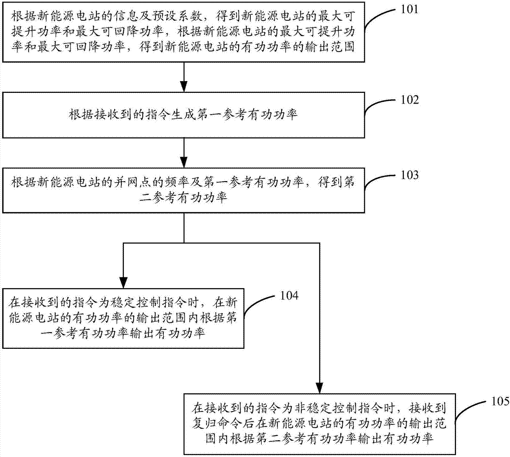
[0052] figure 1 It is a flowchart of Embodiment 1 of the method for controlling the active power of a new energy power station according to the present invention, as shown in figure 1 As shown, the method for controlling the active power of a new energy power station provided by the embodiment of the present invention can be applied to a device for controlling the active power of a new energy power station (hereinafter referred to as the device), and the method may include the following steps:

[0053] Step 101. According to the information and preset coefficients of the new energy power station, obtain the maximum boostable power and the maximum retractable power of the new energy power station, and obtain the new energy power station according to the maximum boostable power ...


PUM


Abstract

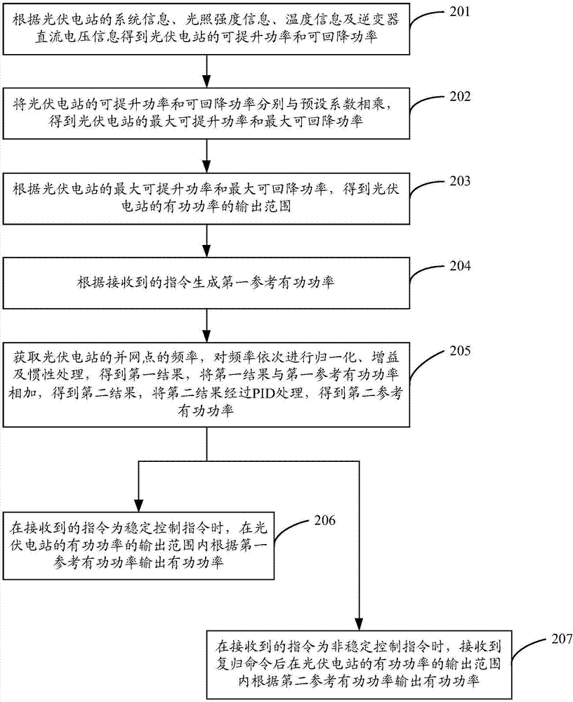
The invention discloses a new energy power station active power controlling method comprising the following steps: obtaining the maximum liftable power and the maximum falling power of a new energy power station according to the information and preset coefficients of the new energy power station; obtaining the output range of the active power of the new energy power station according to the maximum liftable power and the maximum falling power of the new energy power station; forming the first reference active power according to a received order; obtaining the second reference active power according to the frequency of the grid connected point of the new energy power station and the first reference active power; outputting the active power according to the first reference active power in the output range of the active power of the new energy power station when the received order is a stable control order; receiving a reset order, and outputting the active power according to the second reference active power in the output range of the active power of the new energy power station when the received order is a non-stable control order. The invention also discloses a new energy power station active power controlling device and equipment.

Description

technical field [0001] The invention relates to the technical field of new energy power generation, in particular to a method, device and equipment for controlling the active power of a new energy power station. Background technique [0002] New energy power generation technologies represented by wind power and photovoltaics have developed rapidly in recent years, and the proportion of new energy installed capacity in some areas has been quite high; due to the intermittent and fluctuating characteristics of new energy output, the safe and stable operation of the power system is facing great challenges. The power grid needs to fully exploit the regulation capacity to make up for the intermittency of new energy output, so as to ensure continuous and reliable power supply to the load; at present, at a specific moment, when the power grid operating parameters (frequency, voltage, etc.) are abnormal or fail, The active power adjustment method is mostly manual adjustment. Due to t...

Claims


Application Information

Patent Timeline
Patent Type & Authority Applications(China)
IPC IPC(8): H02J3/48H02J3/38H02J3/42
CPCH02J3/383H02J3/42H02J3/48Y02E10/56
Inventor 孙光辉韩连山王新宝王淑超王君超朱晓彤沈全荣
Owner NR ELECTRIC CO LTD
Learn More