Apparatus and method for detecting shock resistance of concrete

A technology of impact resistance and detection device, applied in the direction of measuring device, strength characteristics, instruments, etc., can solve the problems of inability to complete the concrete strength test, the force of the specimen is scattered, and the cumbersome scope of application, so as to achieve rapid impact resistance detection, Stable landing area, easy to use effect

Active Publication Date: 2018-04-27
SOUTHEAST UNIV
View PDF10 Cites 5 Cited by
  • Summary
  • Abstract
  • Description
  • Claims
  • Application Information

AI Technical Summary

Problems solved by technology

[0003] Although the measuring instruments produced by the instrument manufacturers according to the standards can quickly and accurately measure the impact resistance of concrete, there are several deficiencies: first, the user purchases instruments to increase the cost, which is expensive for small scientific research projects and ordinary construction inspections; The device is not easy to carry, and the concrete strength test for outdoor construction sites cannot be completed
For the use of the self-made test device, there are also the following

Method used


Image

  • Apparatus and method for detecting shock resistance of concrete
  • Apparatus and method for detecting shock resistance of concrete
  • Apparatus and method for detecting shock resistance of concrete

Examples


Embodiment 1

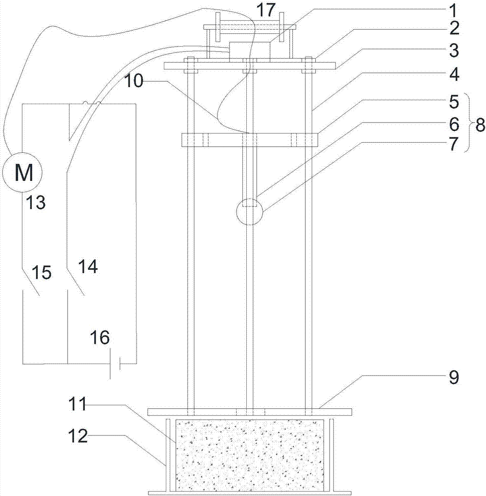
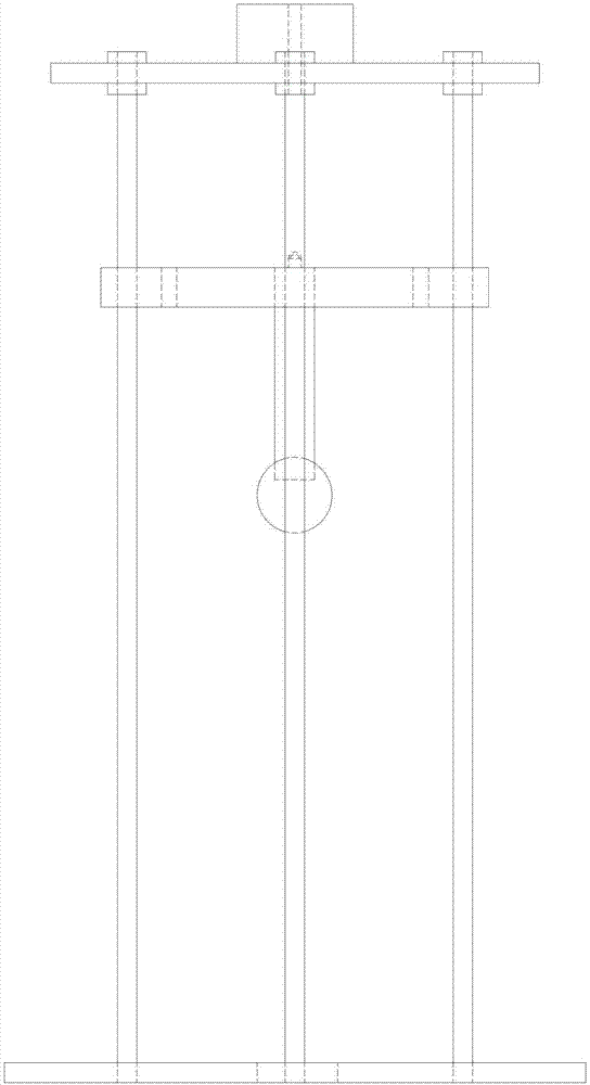
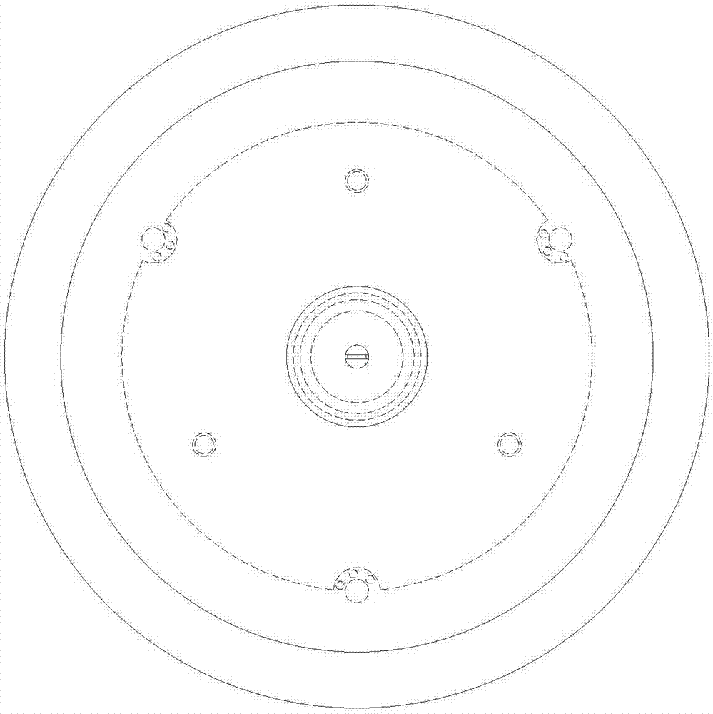
[0040] It can be seen from the accompanying drawings that the detection device for the impact resistance of concrete includes a chassis and an impact device. The chassis is placed above the concrete test block. The center of the chassis is provided with an impact hole, and several guide rails are vertically arranged on the chassis. The impact device can climb and descend on the guide rail rod, and when the impact device falls, it passes through the impact hole and impacts on the concrete test block.

[0041] The impact device includes a gravity plate, a punch and an impact ball, the periphery of the gravity plate runs through the guide rail rod, the punch is set at the center of the lower surface of the gravity plate, and the impact ball is set at the end of the punch.

[0042] A top plate is provided through the top of the guide rail rod, and the top plate is screwed to the guide rail rod.

[0043]The center of the top plate is provided with an electromagnet, and the electrom...

Embodiment 2

[0049] In order to be able to impact and crack concrete test blocks with strong impact resistance, the present invention can set a plurality of impact attachment weights to increase the impact energy. Impact blocks are arranged at the ends of the rods, and any symmetrically arranged impact blocks have the same weight and symmetrical shape. The weight of the impact block can be different, and the shape of the impact block is not limited, as long as the symmetry is guaranteed to prevent the impact device from deflecting when it falls freely.

[0050] Other features are consistent with Example 1.

Embodiment 3

[0052] In order to adapt to concrete test blocks of different sizes and different impact resistance properties, impact blocks of different sizes and shapes were replaced to match the performance of the concrete test blocks, and other features were consistent with those of Example 1.


PUM


Abstract

The invention discloses an apparatus and a method for detecting shock resistance of concrete. The apparatus for detecting shock resistance of concrete comprises a chassis and an impact device; the chassis is placed over a concrete test block, the center of the chassis is provided with an impact hole in breakthrough, and the chassis is vertically provided with several guide rail rods; the impact device can climb on the guide rail rods and freely fall off, and the impact device can freely fall off from the guide rail rods and transverses the impact hole and impacts on the concrete test block. The method for detecting shock resistance of concrete comprises the following steps: a step 1, at least five concrete test blocks are poured; a step 2: the apparatus for detecting shock resistance of concrete is installed; a step 3: a motor with forward or reverse rotation is provided; a step 4: shock-testing is carried out; a step 5: the step 4 is repeated till the concrete test block appears cracking or penetrated cracks; a step 6: site clearing is carried out. The apparatus has small volume and is easy to carry, and shock resistance detection of the concrete can be rapidly completed.

Description

technical field [0001] The invention relates to a detection device and method for the impact resistance performance of concrete, belonging to the field of civil engineering. Background technique [0002] At present, the industry standard formulated by the American Concrete Institute (ACI) is generally adopted for the detection of the impact resistance of concrete. The continuous free-fall impact test is carried out on standard concrete samples using the falling weight method. The American ACI544 committee recommends the use of the following for the calculation of the impact energy of concrete: W=n*m*g*H ( W is the impact energy; n is the number of impacts; H is the falling height of the hammer; m is the mass of the hammer; g is the acceleration of gravity). According to this specification, many manufacturers at home and abroad produce corresponding test and measuring instruments, such as the XJL-300C drop weight test device of Hebei Chengde Hengtong Test and Inspe...

Claims


Application Information

Patent Timeline
IPC IPC(8): G01N3/303
CPCG01N3/303
Inventor 黄侨郑华凯宋晓东徐轶昀
Owner SOUTHEAST UNIV
Why Eureka
Try Eureka