Automatic temperature control laser

An automatic temperature control, laser technology, applied in non-electric variable control, instrument, temperature control and other directions, can solve the problem of small temperature range, and achieve the effect of reducing environmental requirements, broadening the scope of use, and reducing costs

Pending Publication Date: 2018-04-27
北京是卓科技有限公司
View PDF6 Cites 0 Cited by
  • Summary
  • Abstract
  • Description
  • Claims
  • Application Information

AI Technical Summary

Problems solved by technology

[0003] The purpose of the present invention is to provide a laser with automatic temperature cont

Method used


Image

  • Automatic temperature control laser
  • Automatic temperature control laser
  • Automatic temperature control laser

Examples


Example Embodiment

[0027] The technical solutions of the present invention will be clearly and completely described below in conjunction with the accompanying drawings. Obviously, the described embodiments are part of the embodiments of the present invention, rather than all of them. Based on the embodiments of the present invention, all other embodiments obtained by those of ordinary skill in the art without creative work shall fall within the protection scope of the present invention.

[0028] In the description of the present invention, it should be noted that the terms "center", "upper", "lower", "left", "right", "vertical", "horizontal", "inner", "outer", etc. The indicated orientation or positional relationship is based on the orientation or positional relationship shown in the drawings, which is only for the convenience of describing the present invention and simplifying the description, rather than indicating or implying that the pointed device or element must have a specific orientation or ...


PUM


Abstract

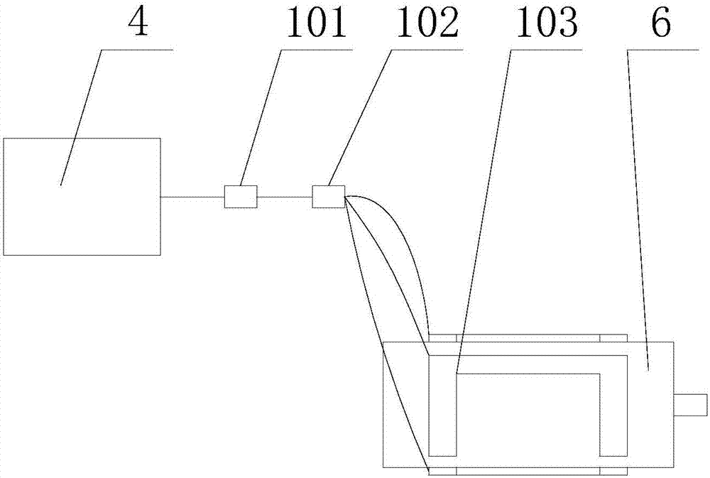
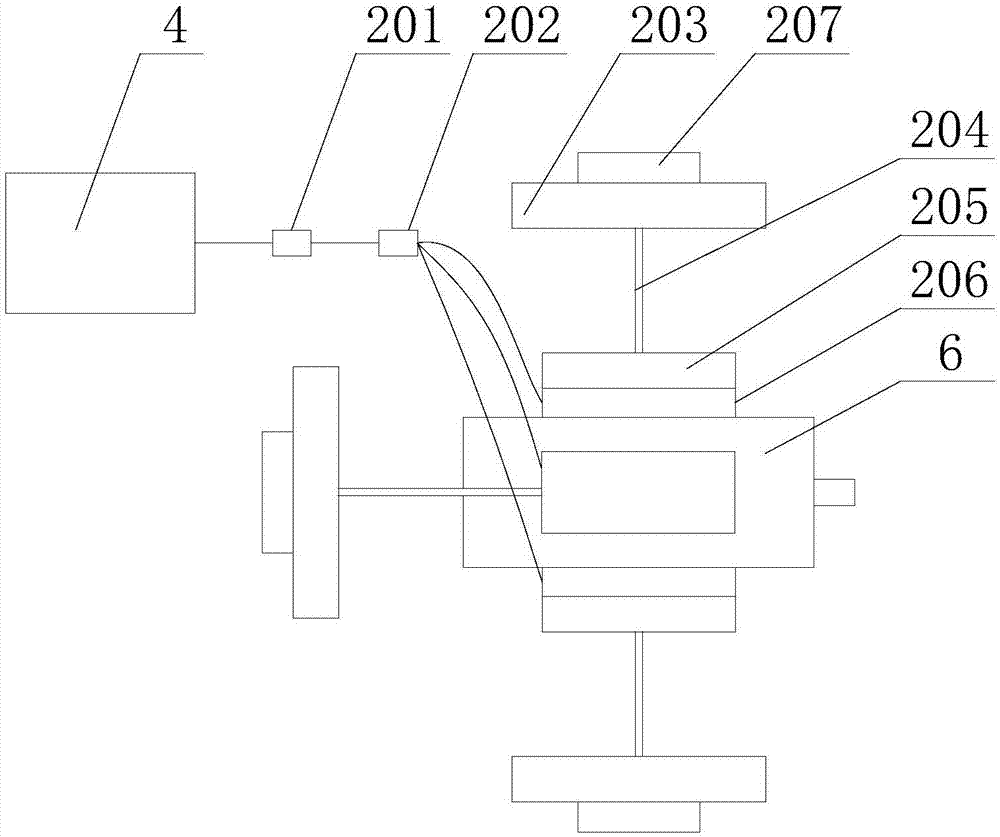
The invention relates to the technical field of laser equipment, and in particular relates to an automatic temperature control laser. The laser comprises a laser module, a control module, a temperature acquisition module, a refrigeration module, a heating module and a user interaction module. The user interaction module, the temperature acquisition module, the refrigeration module and the heatingmodule are connected with the control module respectively. The invention provides the automatic temperature control laser to solve the problem of small temperature range of the use environment of theexisting laser.

Description

technical field [0001] The invention relates to the technical field of laser equipment, in particular to a laser with automatic temperature control. Background technique [0002] With the development of science and technology, more and more solid-state lasers and semiconductor lasers have replaced traditional light sources and are used in various fields, such as: remote sensing measurement, security, communication and so on. However, the optimum operating temperature of the laser is 25±10°C. When the operating temperature is higher or lower than this temperature range, the laser emission power will be reduced (continuous emission type laser), and the laser frequency will be reduced (pulse type laser). The working life will also be affected and reduced, and what's more, the laser will be damaged. Therefore, in order to make the laser work normally, the traditional method usually places the laser indoors or in an air-conditioned work box, which not only limits the use of the ...

Claims


Application Information

Patent Timeline
IPC IPC(8): G05D23/22
CPCG05D23/22
Inventor 张志伟
Owner 北京是卓科技有限公司
Why Eureka
Try Eureka