Supercharge Your Innovation With Domain-Expert AI Agents!

Asymmetrically synchronous reluctance motor rotor lamination

A synchronous reluctance motor, rotor punching technology, applied in the direction of magnetic circuit rotating parts, magnetic circuit, electrical components, etc., can solve the problems of large electromagnetic noise and electromagnetic vibration, large torque pulsation of synchronous reluctance motor, etc. The effect of improving the quality of operation

Inactive Publication Date: 2018-04-27
WOLONG ELECTRIC GRP CO LTD
View PDF8 Cites 2 Cited by
  • Summary
  • Abstract
  • Description
  • Claims
  • Application Information

AI Technical Summary

Problems solved by technology

[0002] At present, the rotor punching plates of synchronous reluctance motors are basically designed with a symmetrical and uniformly distributed structure, but the synchronous reluctance motors punched with this structure have relatively large torque ripples, which in turn will produce large Electromagnetic Noise and Electromagnetic Vibration

Method used


Image

  • Asymmetrically synchronous reluctance motor rotor lamination
  • Asymmetrically synchronous reluctance motor rotor lamination
  • Asymmetrically synchronous reluctance motor rotor lamination

Examples


example 1

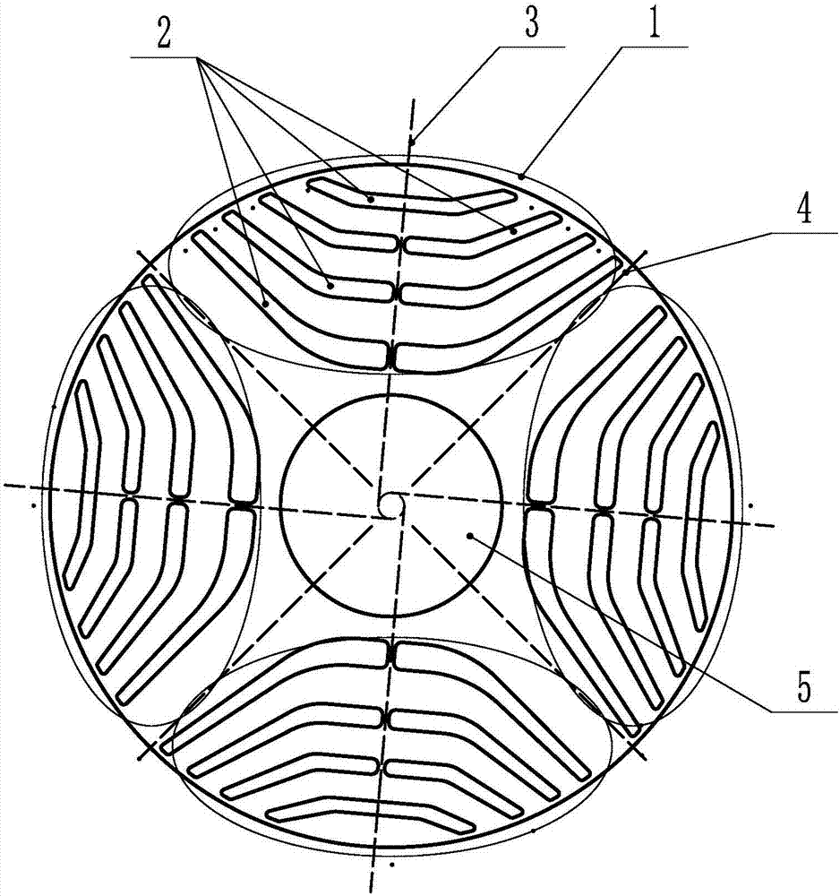
[0026] Such as figure 1 As shown, an asymmetric synchronous reluctance motor rotor stamping, the rotor stamping has 4 sets of hole slots, the area where each set of hole slots is located forms a magnetic pole 1, a total of 4 magnetic poles 1 are formed, and the hole slots are reluctance slots 2 , the center of the rotor punch has a shaft hole 5, the geometric center line of the magnetic pole 1 is the magnetic pole axis 3, the symmetrical axis of the two adjacent magnetic pole axes 3 is the non-magnetic pole axis 4, the rotor punch is an asymmetric structure, each magnetic pole The reluctance slot 2 of 1 is asymmetrical with respect to the magnetic pole axis 3. The reluctance slot 2 includes an outer slot located outside the magnetic pole 1, and three inner slots located between the outer slot and the shaft hole 5. Both the outer slot and the inner slot include The flat groove located in the middle of the magnetic pole 1 and the left and right inclined grooves connected with th...

example 2

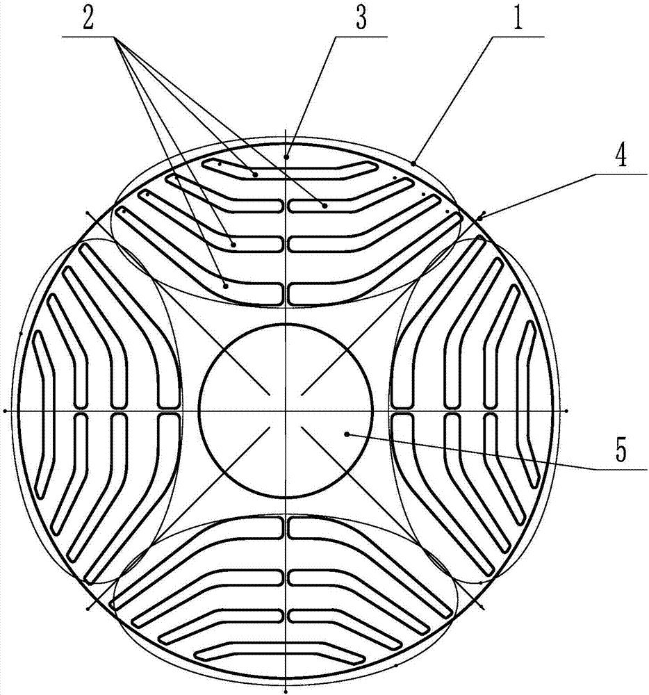
[0029] Such as figure 2 As shown, the difference from the first example above is that for an asymmetric synchronous reluctance motor rotor punching, two adjacent magnetic poles 1 are symmetrical about the non-magnetic pole axis 4 .

example 3

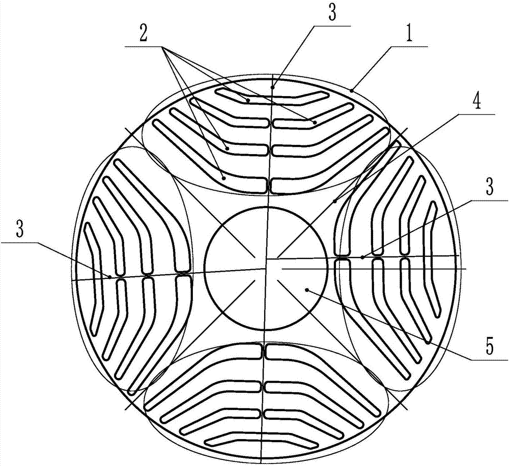
[0031] Such as image 3 As shown, the difference from the first example above is that for an asymmetric synchronous reluctance motor rotor punching, the angles between two adjacent magnetic pole axes 3 are not equal; the adjacent two non-magnetic pole axes 4 The angles between them are not equal.


PUM


Abstract

The invention discloses an asymmetrically synchronous reluctance motor rotor lamination, and relates to the field of synchronous reluctance motors. Symmetrical laminations with uniform distribution circumferentially are adopted, the synchronous reluctance motor is of relatively high torque ripple, and then relatively large electromagnetic noise and electromagnetic vibration are generated. According to the asymmetrically synchronous reluctance motor rotor lamination, a plurality of groups of hole holes are formed in the rotor lamination, a magnetic pole is formed in the area where each group ofhole grooves is formed, the hole grooves are reluctance grooves, an axle hole is formed in the center of the rotor lamination, the rotor lamination is of an asymmetrical structure, and the reluctancegroove, including each magnetic pole, in the asymmetrical structure is asymmetrical about the axis of the magnetic pole and / or the extension cords of the axes of the magnetic poles are not intersected in one point. Through the technical scheme, through the asymmetrical structure of the rotor lamination, the torque ripple is reduced, and then the electromagnetic noise and electromagnetic vibrationduring motor operation are reduced.

Description

technical field [0001] The invention relates to the field of synchronous reluctance motors, in particular to an asymmetrical synchronous reluctance motor rotor stamping. Background technique [0002] At present, the rotor punching plates of synchronous reluctance motors are basically designed in a symmetrical and uniformly distributed structure. Electromagnetic noise and electromagnetic vibration. In order to solve this problem, the present invention proposes a new rotor lamination for synchronous reluctance motors, which can effectively suppress or reduce electromagnetic noise and electromagnetic vibration problems caused by torque ripples of reluctance motors. Contents of the invention [0003] The technical problem to be solved and the technical task proposed by the present invention are to perfect and improve the existing technical solutions, and to provide an asymmetrical synchronous reluctance motor rotor stamping for the purpose of effectively reducing electromagne...

Claims


Application Information

Patent Timeline
Patent Type & Authority Applications(China)
IPC IPC(8): H02K1/22
CPCH02K1/22H02K2201/06
Inventor 胡吉亮严伟灿王国龙王斌孙军建
Owner WOLONG ELECTRIC GRP CO LTD
Features
  • R&D
  • Intellectual Property
  • Life Sciences
  • Materials
  • Tech Scout
  • Unparalleled Data Quality
  • Higher Quality Content
  • 60% Fewer Hallucinations
Learn More