Clinker production line for novel dry process cement kiln and denitration process method for clinker production line

A dry-process cement and production line technology, applied in clinker production, cement production, etc., can solve the problems of inapplicability, affecting the stable operation of the system, large coal feeding power, etc., and achieve the suppression of fuel-type NOx generation, operation quality and stability Performance improvement and reduction of NOx production

Active Publication Date: 2013-02-13
ANHUI CONCH GRP +2
View PDF3 Cites 18 Cited by
  • Summary
  • Abstract
  • Description
  • Claims
  • Application Information

AI Technical Summary

Problems solved by technology

[0037] (1) The skinning phenomenon in the reduction area is serious, which affects the normal and stable operation of the system, making it difficult to maintain production, resulting in the inability to apply this technology or dismantle the technical facilities in actual production;
[0038] (2) Strict requirements on the quality of raw materials and fuels, especially anthracite with low volatile content is less effective;
[0039] (3) Strict requirements on process operation, need to control kiln tail O 2 The content is below 2%, which is difficult to achieve in actual operation;
[0040] (4) It is necessary to add a separate coal feeding metering system and a larger coal feeding power;
[0041] (5) The denitrification efficiency is unstable, and it is difficult to reach 30%;
[0042] (6) The denitrification transformation has a large workload, a long time, a large investment, and an increase in operating costs

Method used


Image

  • Clinker production line for novel dry process cement kiln and denitration process method for clinker production line
  • Clinker production line for novel dry process cement kiln and denitration process method for clinker production line
  • Clinker production line for novel dry process cement kiln and denitration process method for clinker production line

Examples


Embodiment Construction

[0075] The specific implementation of the present invention will be described in further detail below by describing the embodiments with reference to the accompanying drawings, so as to help those skilled in the art have a more complete, accurate and in-depth understanding of the inventive concepts and technical solutions of the present invention.

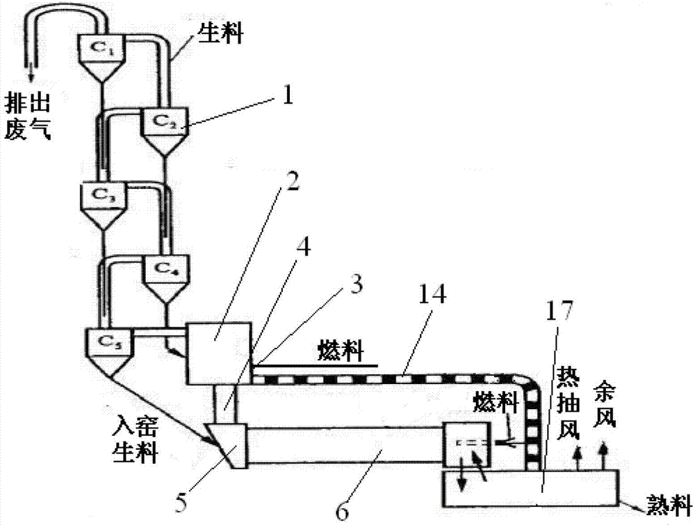
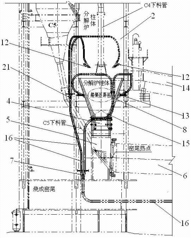
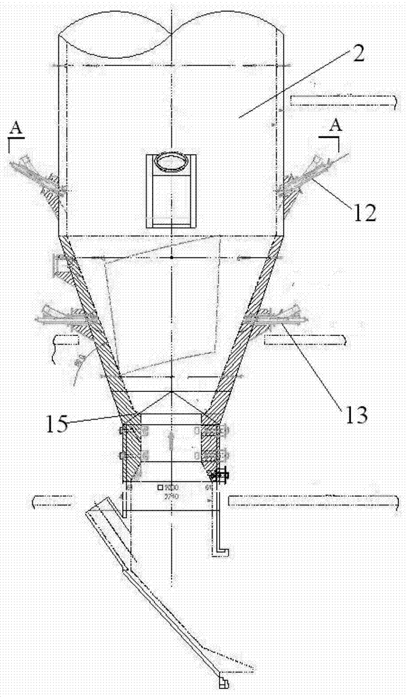
[0076] Such as figure 1 The structure of the present invention expressed is a new dry-process cement kiln clinker production line and its denitrification process, including a cyclone 1, a calciner 2, a burner 3, a tertiary air duct 14, a kiln tail ascending flue 4, and a kiln tail Smoke chamber 5 and rotary kiln 6. The present invention is a NOx emission reduction technology completely different from the staged combustion of the prior art.

[0077] Such as Figure 6 As shown, the air duct 1 includes two columns from top to bottom: C1A, C2A, C3A, C4A, C5A; C1B, C2B, C3B, C4B, C5B.

[0078] Figure 6 It also stated that the new d...


PUM

PropertyMeasurementUnit
heightaaaaaaaaaa
sizeaaaaaaaaaa

Abstract

The invention discloses a clinker production line for a novel dry process cement kiln. Pulverized coal in a pulverized coal pipeline which is communicated with the tail of the kiln is divided into two channels by a first pulverized coal distributor, wherein one channel is communicated with a column body on the upper part of a decomposition furnace, and the pulverized coal is divided into two channels again by a second pulverized coal distributor and symmetrically enters the column body on the upper part of the decomposition furnace; and the other channel is communicated with a cone on the lower part of the decomposition furnace, and the pulverized coal is divided into two channels again by the second pulverized coal distributor and symmetrically enters the cone on the lower part of the decomposition furnace. The invention also provides a denitration process method adopted by the production line. By the technical scheme, thermal NOx generated in the kiln is decreased and reduced, and the generation of fuel NOx is inhibited, so that NOx can be effectively reduced from the source; and after process improvement, operation parameters are optimized, the operation quality and stability of the system are promoted, and a certain energy-saving effect is achieved.

Description

technical field [0001] The invention belongs to the technical field of cement production, and relates to the production technology of a new type of dry process cement kiln. More specifically, the invention relates to a new type of dry process cement kiln clinker production line. In addition, the invention also relates to the denitrification process of the production line . Background technique [0002] 1. Technical background of denitrification in cement clinker production line: [0003] At present, my country has nearly 5,000 cement enterprises, and its output has ranked first in the world for many years. In 2011, the country's cumulative total cement output was 2.09 billion tons, of which the proportion of new dry process cement reached 80.9%. By the end of 2011, more than 1,500 new dry-process cement production lines have been built using domestic technology and equipment. [0004] The emission reduction of nitrogen oxides has become a major problem restricting my coun...

Claims


Application Information

Patent Timeline
Patent Type & Authority Applications(China)
IPC IPC(8): C04B7/44
CPCY02P40/121
Inventor 张长乐盛赵宝轩红钟杨旺生邵明军汪克春程占
Owner ANHUI CONCH GRP
Why Eureka
Try Eureka