Electric equipment polling method and device

A technology of power equipment and equipment, applied in the field of power equipment inspection methods and devices, can solve problems such as consuming a lot of time, taking a long time, reducing the safety of power grid operation, economy and high efficiency, etc., to provide security and increase the overall Effect of life cycle, improvement of inspection efficiency and operation quality

Inactive Publication Date: 2018-02-16
ELECTRIC POWER RESEARCH INSTITUTE, CHINA SOUTHERN POWER GRID CO LTD +1
View PDF3 Cites 15 Cited by
  • Summary
  • Abstract
  • Description
  • Claims
  • Application Information

AI Technical Summary

Problems solved by technology

[0002] With the continuous expansion of the power grid structure, the grid structure is becoming more and more complex, the number of power equipment is increasing, and power failures such as power outages continue to occur. However, the number of power equipment and the number of failures are increasing year by year and the number of inspection personnel that basically maintains zero growth forms a clear contrast.
[0003] The traditional inspection method is usually carried out according to the plan, but when an emergency occurs, it is often necessary to temporarily dispatch inspectors to the scene as soon as possible, and the management personnel cannot grasp the status of the inspectors in real time, which takes a lot of time Verify the status of patrol personnel by phone, and then assign emergency tasks to the most suitable personnel
The personnel deployment process is time-consuming and inefficient, which is not conducive to quickly verifying and handling power emergencies
[0004] Due to the lack of real-time deployment of inspection personnel, under the condition of limited manpower and material resources, the efficiency and operation quality of equipment inspection are reduced, the life cycle of equipment is shortened, and the safety, economy and efficiency of power grid operation are reduced.

Method used


Image

  • Electric equipment polling method and device
  • Electric equipment polling method and device
  • Electric equipment polling method and device

Examples


Embodiment Construction

[0028] In order to make the purpose, technical solution and advantages of the present invention clearer, the method and device for inspection of electric power equipment of the present invention will be further described in detail below through embodiments and in conjunction with the accompanying drawings.

[0029] It should be understood that, unless otherwise defined, all technical and scientific terms used herein have the same meaning as commonly understood by one of ordinary skill in the technical field of the invention. The terms used herein in the description of the present invention are for describing specific embodiments only, and are not intended to limit the present invention.

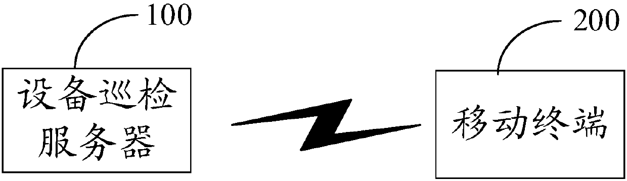
[0030] figure 1 It is an application environment diagram of an inspection method for electrical equipment in an embodiment, the application environment includes an equipment inspection server 100 and a mobile terminal 200, and the equipment inspection server 100 communicates with the mobile t...


PUM


Abstract

The invention relates to an electric equipment polling method and device, and relates to the technical field of electric systems. the method comprises the following steps of: obtaining a polling demand signal of electric equipment by an equipment polling server and sending the polling demand signal to a mobile terminal corresponding to each polling staff; acquiring work information of corresponding polling staff by each mobile terminal according to the polling demand signal and sending the work information to the equipment polling server; and determining an appointed polling staff by the equipment polling server according to the work information of each polling staff, generating a polling task according to the polling demand signal and sending the polling task to the mobile terminal corresponding to the appointed polling staff. Through the method, the assignment instantaneity of the polling staffs is improved, the equipment polling efficiency and operation quality are improved under the limited manpower and material resources, the full life cycle of the equipment is prolonged, and safety, economy and high efficiency are provided for power grid operation.

Description

technical field [0001] The invention relates to the technical field of power systems, in particular to a power equipment inspection method and device. Background technique [0002] With the continuous expansion of the power grid structure, the grid structure is becoming more and more complex, the number of power equipment is increasing, and power failures such as power outages continue to occur. However, the number of power equipment and the number of failures are increasing year by year and the number of inspectors who basically maintains zero growth forms a clear contrast. [0003] The traditional inspection method is usually carried out according to the plan, but when an emergency occurs, it is often necessary to temporarily dispatch inspectors to the scene as soon as possible, and the management personnel cannot grasp the status of the inspectors in real time, which takes a lot of time Verify the status of the inspection personnel by phone, and then assign emergency task...

Claims


Application Information

Patent Timeline
Patent Type & Authority Applications(China)
IPC IPC(8): G06Q10/06G06Q10/00G06Q50/06
Inventor 陈浩敏郭晓斌陈波蒋愈勇王建邦谈赢杰杨占杰席禹
Owner ELECTRIC POWER RESEARCH INSTITUTE, CHINA SOUTHERN POWER GRID CO LTD
Why Eureka
Try Eureka