
Electrically driven air pump and method for the production thereof

an air technology, applied in the direction of pump components, piston pumps, non-positive displacement fluid engines, etc., can solve the problems of premature reach of the operating temperature required for a regulated catalyzer, increased running noise, and electric motor in this prior art electrically driven air pump is counterbalanced with an installed pump wheel, so as to reduce vibration and reduce running noise.

Inactive Publication Date: 2009-04-21
ROBERT BOSCH GMBH
View PDF12 Cites 15 Cited by
  • Summary
  • Abstract
  • Description
  • Claims
  • Application Information

AI Technical Summary

Benefits of technology

[0006]The invention is based on the objective of creating a method to manufacture an electric air pump with reduced vibrations and therefore also inherently reduced running noise. It is also the objective of the present invention to make such an air pump available.
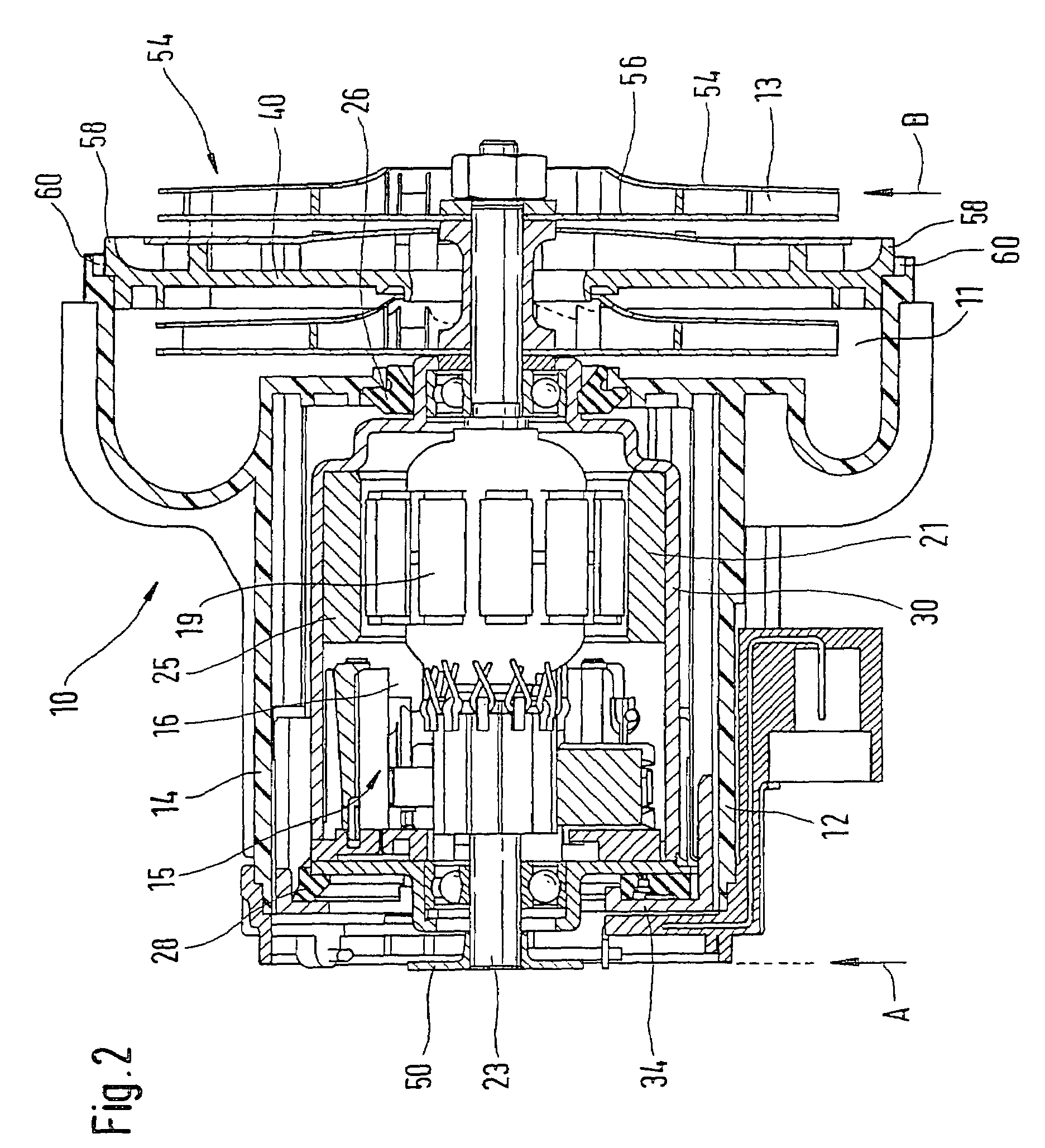
[0008]The method in accordance with the invention to manufacture an electrically driven air pump improves the air pump known from the prior art with respect to its running quality. In the case of the manufacturing method in accordance with the invention, the air pump, which features a housing in which a pump mechanism with at least one fan wheel as well as an electric motor driving the at least one fan wheel are integrated, is counterbalanced with the electric motor already built into the housing via balancing in at least two planes that are spaced apart axially. Because of this two-plane balancing, the balance quality of the electrically driven air pump in accordance with the invention is clearly increased so that manufacturing tolerances can be further reduced in the running noise of the pump.
[0013]The electric motor of the air pump is isolated vibrationally from the pump housing via elastic means. This produces a further reduction in the vibrations of the driving motor on the pump housing. In the case of the method in accordance with the invention to manufacture an electrically driven air pump, when balancing the air pump, the balancing rpm and / or the manner of incorporating the balancing is coordinated with the natural frequency of the isolation means. Typically the air pump in accordance with the invention is counterbalanced in an rpm range that is clearly below the frequency of resonance of the isolation means. It is possible in this way to minimize the effect of the elastic coupling means between the electric motor and the pump housing on the running behavior of the air pump.
[0017]The electrically driven air pump in accordance with the invention features a housing, which has a cover on the fan wheel side and a cover on the motor side. In the case of the method to manufacture an electrically driven air pump in accordance with the invention, the completely mounted air pump with covers that are not yet mounted can thus be completely counterbalanced in two planes. Imbalances, which are first yielded for example by installing the electric motor in the pump housing, can be eliminated to a large extent via the resulting complete balancing. Dispersion in the running quality of an air pump, which results from the mechanical isolation elements, can be minimized by the manufacturing method in accordance with the invention. In the case of the method in accordance with the invention, upon termination of the counterbalancing process the pump housing is completed and closed by a cover on the fan wheel side and a cover on the motor side.
[0018]The claimed method to manufacture an electrically driven air pump supplies an air pump, which guarantees extremely high smoothness of running due to its complete balancing in two planes. Because of the strong structure-borne noise isolation, which is achieved via the mechanical isolation of the electric motor and the additional complete counterbalancing in two planes that is conducted in an installed state, it also is possible to use the air pump in accordance with the invention without expensive isolations for the body mountings.

Problems solved by technology

In addition, the afterburning via a secondary air supply system increases the exhaust gas temperature so that the operating temperature required for a regulated catalyzer is reached prematurely.
The vibrations in the air pump that are generated due to imbalances are transmitted to the components that are connected to the air pump and thereby generate increased running noise.
The electric motor in this prior art electrically driven air pump is counterbalanced with an installed pump wheel, in a built-in state, with a not yet closed pump side by placing balancing marks on a running wheel of the pump mechanism.
Because of the balancing process on the installed electric motor, even though the running quality of such an air pump can be increased by the reduction in the vibrations occurring, manufacturing tolerances cannot be avoided from air pump to air pump, however.

Method used


Image

  • Electrically driven air pump and method for the production thereof
  • Electrically driven air pump and method for the production thereof
  • Electrically driven air pump and method for the production thereof

Examples


Embodiment Construction

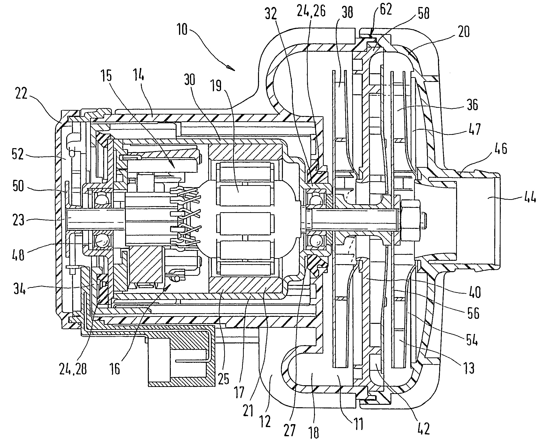
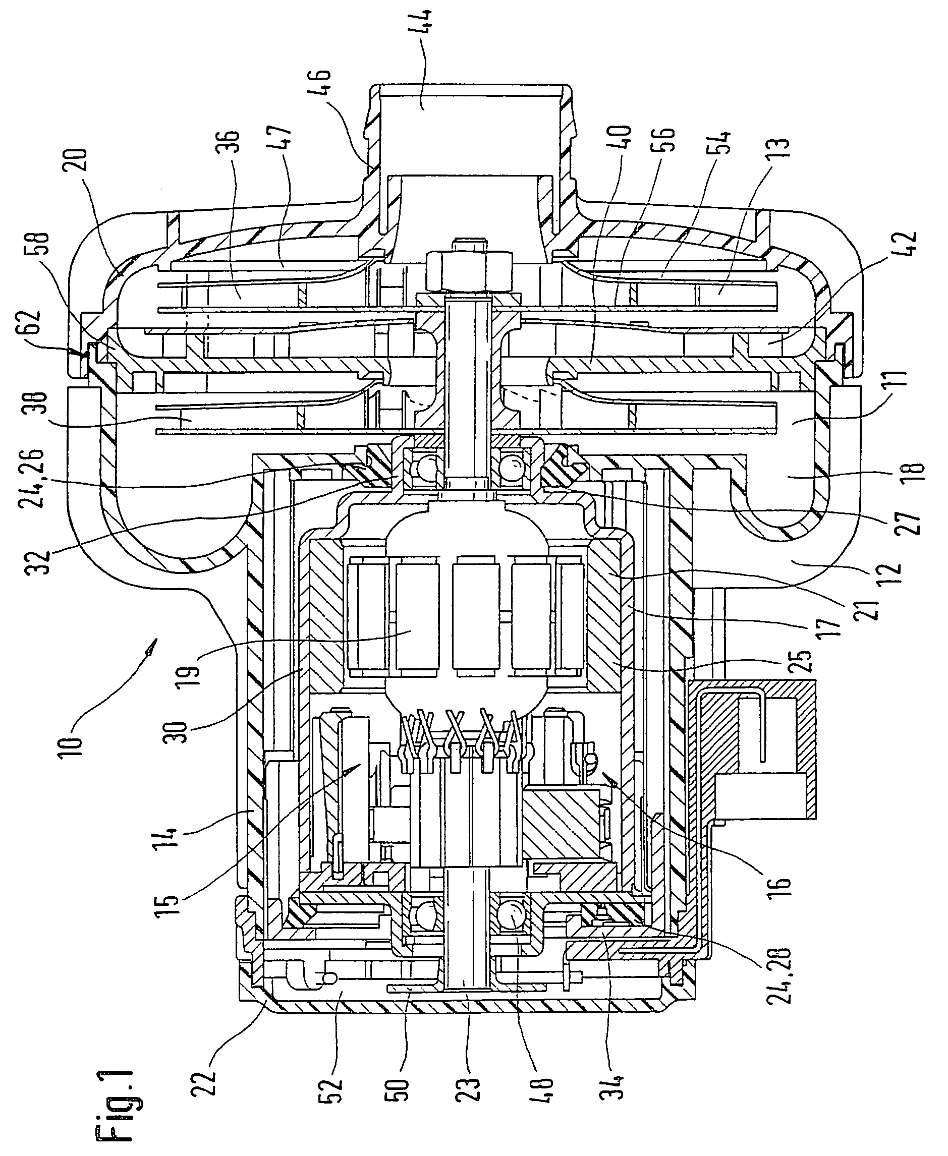
[0024]FIG. 1 shows a longitudinal section through an exemplary embodiment of an electrically driven air pump 10 in accordance with the invention in an installed state. The air pump 10 includes a pump part 11 as well as a drive or motor part 15, which are surrounded by a housing 12. The pump part 11 is composed essentially of a pump mechanism 13 as well as corresponding inlet and outlet openings for the air that is to be conveyed. The pump housing 12 is embodied as essentially three parts in the exemplary embodiment in accordance with FIG. 1. In addition to a central housing part 14, which surrounds the electric motor 16 driving the air pump, the housing 12 features a cover 20 on the pump mechanism side as well as a cover 22 on the driving motor side. The cover 20 on the pump mechanism side has a central opening 44, though which the to-be-compressed air is inducted. The housing 12 of the air pump 10 in accordance with the invention is manufactured in an advantageous manner of a plast...


PUM


Abstract

A method to manufacture a secondary air pump for a motor vehicle with an internal combustion engine, wherein the air pump features a housing, in which a pump mechanism with at least one fan wheel as well as an electric motor driving the at least one fan wheel are arranged. The air pump is counterbalanced with the electric motor built into the housing via balancing in at least two planes that are spaced apart axially.

Description

BACKGROUND OF THE INVENTION[0001]The invention relates to a method to manufacture an electrically driven air pump, in particular a method to manufacture a secondary air pump for a motor vehicle with an internal combustion engine, or such an electrically driven air pump.[0002]Generic air pumps or fans are used for example as secondary air pumps or secondary ventilation fans to inject additional air into the exhaust gas channel of an internal combustion engine of a motor vehicle. This method minimizes the generation of nitrogen oxides or leads to a reduction in the content of carbon monoxides or hydrocarbons in the combustion residues before the exhaust gas reaches the catalyzer of the internal combustion engine. In the case of a secondary air supply, the exhaust gas channel is supplied with fresh air as immediately as possible behind the engine in order to eliminate the hydrocarbon compounds that are generated during the combustion process and the carbon monoxide. Because of the seco...

Claims


Application Information

Patent Timeline
Patent Type & Authority Patents(United States)
IPC IPC(8): F04B35/04F04D29/66
CPCF04D29/662
Inventor LUEDTKE, ULRICHMUSCHELKNAUTZ, CLAUDIUSBURG, FABRICE
Owner ROBERT BOSCH GMBH
Learn More