Flotation machine hollow shaft dredger

A dredge and flotation machine technology, applied in the field of flotation machines, can solve problems such as affecting the stable production of workshops and affecting the operation rate of equipment, and achieve the effects of improving dredging efficiency, improving dredging effect, and increasing dredging range.

Pending Publication Date: 2018-05-01
TIBET HUATAILONG MINING DEV
View PDF0 Cites 3 Cited by
  • Summary
  • Abstract
  • Description
  • Claims
  • Application Information

AI Technical Summary

Problems solved by technology

However, this solution involves the disassembly and assembly of the flotation machine, which not only affects the stable production of the workshop, but also affects the operation rate of the equipment

Method used


Image

  • Flotation machine hollow shaft dredger

Examples


Embodiment Construction

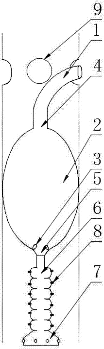
[0023] A hollow shaft dredge of a flotation machine includes a rubber hose 1, an expansion rubber bag 2, a rubber valve 3, and a flushing mechanism. The expansion rubber bag 2 is provided with a fluid inlet 4 and a fluid outlet 5 respectively, and the rubber hose 1 Connected to the fluid inlet 4, the flushing mechanism is connected to the fluid outlet 5. The inner diameter of the expanded rubber bladder 2 when it is not inflated is preferably the same as the inner diameter of the rubber hose 1, so that it can be quickly inserted into the hollow shaft 9; the rubber valve 3 It is arranged in the expanded rubber bladder 2 and the rubber valve 3 is located above the fluid outlet 5. The scouring mechanism includes a scouring tube 6 and a spray head 7. The scouring tube 6 is provided with a plurality of spray holes 8. One end of the scouring tube 6 is connected to the fluid outlet 5, and the other end is connected to the spray head 7. Further, the scouring tube 6 is a telescopic tele...


PUM


Abstract

The invention discloses a flotation machine hollow shaft dredger. The hollow shaft dredger comprises a rubber hose, an expansion rubber bag, a rubber valve and a washing mechanism, wherein a fluid inlet and a fluid outlet are formed in the expansion rubber bag, the rubber hose is connected to the fluid inlet, and the washing mechanism is connected to the fluid outlet; and the rubber valve is arranged in the expansion rubber bag and is located above the fluid outlet. According to the dredger, on the premise of normal production of a workshop, a hollow shaft can be dredged without disassemblinga flotation machine, so that the labor force required by dredging work is greatly reduced, the operation rate of equipment is improved, and the continuous and stable production is guaranteed.

Description

Technical field [0001] The invention relates to the technical field of flotation machines, in particular to a hollow shaft dredger for flotation machines. Background technique [0002] The flotation machine is suitable for the separation of non-ferrous and ferrous metals, and also for the separation of non-metals such as coal fluorite and talc. The flotation machine is driven by the V-belt drive of the motor to rotate the impeller, which produces a centrifugal effect to form a negative pressure. On the one hand, it sucks in sufficient air to mix with the pulp, on the other hand, it stirs the pulp and the medicine, and at the same time refines the foam so that the mineral is bound to the foam. Float to the pulp surface and then form mineralized foam. Adjust the height of the gate to control the liquid level so that the useful foam is scraped out by the scraper. [0003] Concentrators often encounter the problem of blockage of the inflatable hollow shaft of the flotation machine wh...

Claims


Application Information

Patent Timeline
Patent Type & Authority Applications(China)
IPC IPC(8): B03D1/14B08B9/027B08B9/032
CPCB03D1/1487B08B9/027B08B9/0322
Inventor 李磊沈充闫成贵解钊常征王贺强王海青
Owner TIBET HUATAILONG MINING DEV
Why Eureka
Try Eureka