Internal cooling device and method of steel pipe on-line cooling

A technology of cooling device and steel pipe, applied in workpiece cooling device, workpiece surface treatment equipment, metal rolling, etc., can solve the problems of large difference in internal and external cooling rate, insufficient strength margin, uneven structure, etc. The consistency of the organization, the improvement of the comprehensive mechanical properties, the effect of expanding the specifications

Active Publication Date: 2018-05-01
BAOSHAN IRON & STEEL CO LTD
View PDF5 Cites 2 Cited by
  • Summary
  • Abstract
  • Description
  • Claims
  • Application Information

AI Technical Summary

Problems solved by technology

[0002] It is very difficult to implement internal cooling of the steel pipe in progress. Most of the previous online cooling of steel pipes used water spray rings. Nozzles were installed on the water spray rings. The cooling water sprayed by the nozzles only cooled the outer surface of the steel pipes. For thin-walled steel pipes ( 20mm or less) or thicker steel plates with good hardenability can be effectively hardened, but for thick-walled steel pipes or steel pipes with poor hardenability, they cannot be hardened through, which will cause a large difference in cooling rate inside and outside, and it is easy to Inhomogeneity of the structure due to large differences between the inner and outer walls or abnormally coarse tissue, and problems such as inconsistent strength or insufficient strength margin

Method used


Image

  • Internal cooling device and method of steel pipe on-line cooling
  • Internal cooling device and method of steel pipe on-line cooling

Examples


Embodiment Construction

[0023] The present invention will be further described below in conjunction with the accompanying drawings and specific embodiments.

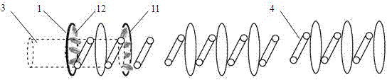
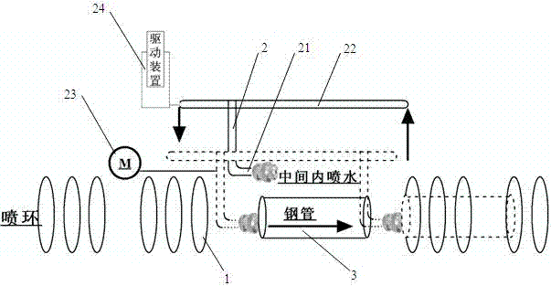
[0024] see figure 1 with figure 2 , an internal cooling device for on-line cooling of steel pipes, which is a part of the on-line spray ring cooling device for steel pipes. The steel pipe online spray ring cooling device includes multiple groups of water spray rings, each group of water spray rings 1 is composed of several water spray ring bodies 11 arranged in front and back, and several nozzles 12 are installed on the water spray ring body 11 along the periphery of the ring , multiple groups of water spray rings 1 are fixedly installed on the cooling roller table 4 line, and spray water to cool the steel pipe 3 placed on the cooling roller table line. Most of the water spray rings in the online spray ring cooling device for steel pipes directly spray water to cool the outer surface of the steel pipe, and some of the water spray rings spray...


PUM


Abstract

The invention relates to an on-line heat treatment technology of steel pipe production, in particular to an internal cooling device and method for steel pipe on-line cooling. According to the internalcooling device and method for steel pipe on-line cooling, the internal cooling device for spraying water from the head part or the tail part into a steel pipe is arranged at the front part, the backpart or the middle part of a steel pipe on-line spraying ring cooling device, and a movable inner spraying axial flow cooling device is arranged at the gap position in the steel pipe on-line sprayingring cooling device, wherein the movable inner spraying axial flow cooling device (2) comprises an up-and-down lifting driving device (24), a front-and-back movement driving device (23), a support (22) and a movable inner spraying axial flow spray pipe (21), so that the temperature difference between the inner wall of the steel pipe and the outer wall of the steel pipe is reduced, the on-line cooling uniformity is improved, the comprehensive mechanical property of the steel pipe is effectively improved, the specification of steel pipes capable of being cooled can be expanded, and the uniformity of the temperature of the inner wall and temperature of the outer wall and the consistency of the radial structure of steel pipe on-line cooling are realized, the production rhythm of on-line hot rolling of the steel pipe is not influenced, and the production efficiency is improved; the production of double-length steel pipes or triple-length steel pipes can also be met; and the length of the steel pipe capable of being cooled is close to 40m or even longer.

Description

technical field [0001] The invention relates to on-line heat treatment technology for steel pipe production, in particular to an internal cooling device and method for on-line cooling of steel pipes. Background technique [0002] It is very difficult to implement internal cooling of the steel pipe in progress. Most of the previous online cooling of steel pipes used water spray rings. Nozzles were installed on the water spray rings. The cooling water sprayed by the nozzles only cooled the outer surface of the steel pipes. For thin-walled steel pipes ( 20mm or less) or thicker steel plates with good hardenability can be effectively hardened, but for thick-walled steel pipes or steel pipes with poor hardenability, they cannot be hardened through, which will cause a large difference in cooling rate inside and outside, and it is easy to There are large differences between the inner and outer walls or abnormally coarse tissue, resulting in uneven tissue, and at the same time, ther...

Claims


Application Information

Patent Timeline
Patent Type & Authority Applications(China)
IPC IPC(8): B21B45/02B21B37/76
CPCB21B37/76B21B45/0203B21B45/0215B21B2045/0227
Inventor 王笑波吴建峰刘晔吕卫东
Owner BAOSHAN IRON & STEEL CO LTD
Why Eureka
Try Eureka