Passive heat-reduction and drag-reduction device and method for high-velocity flow-around boundary layer

A drag reduction device and boundary layer technology, applied in the direction of drag reduction, affecting the air flow through the surface of the aircraft, transportation and packaging, etc. problems, to improve the ability to resist aerodynamic heating, reduce friction and heat flow increments, and suppress turbulent energy transport.

Active Publication Date: 2018-05-01
CHINA ACAD OF AEROSPACE AERODYNAMICS
View PDF4 Cites 14 Cited by
  • Summary
  • Abstract
  • Description
  • Claims
  • Application Information

AI Technical Summary

Problems solved by technology

So far, for the situation where the Mach number of the incoming flow is not less than 3.5, neither a mature heat reduction an

Method used


Image

  • Passive heat-reduction and drag-reduction device and method for high-velocity flow-around boundary layer
  • Passive heat-reduction and drag-reduction device and method for high-velocity flow-around boundary layer
  • Passive heat-reduction and drag-reduction device and method for high-velocity flow-around boundary layer

Examples


Embodiment

[0065] According to measurements by using different wind tunnels and different test techniques, the principle of reducing heat and drag in the high-speed boundary layer proposed by the present invention and the technology for reducing heat and drag in the high-speed boundary layer developed accordingly are correct. Figure 15 Shown is the test model of FD-20 impulse wind tunnel, the test condition is Mach number Ma=5, unit Reynolds number Re=9*10 6 / m, transient heat flow measurements in a pulsed wind tunnel using thin-film resistance thermometers.

[0066] Figure 16 It shows that after adding diamond-shaped rough elements in the laminar flow region (at the vertical line) near the transition, the transition position is obviously delayed. In the figure, x is the position of the model along the flow direction from the head of the model, and Q is the heat flow.

[0067] Figure 17 It is shown that after adding rough elements in the fully developed turbulent region (vertical li...


PUM


Abstract

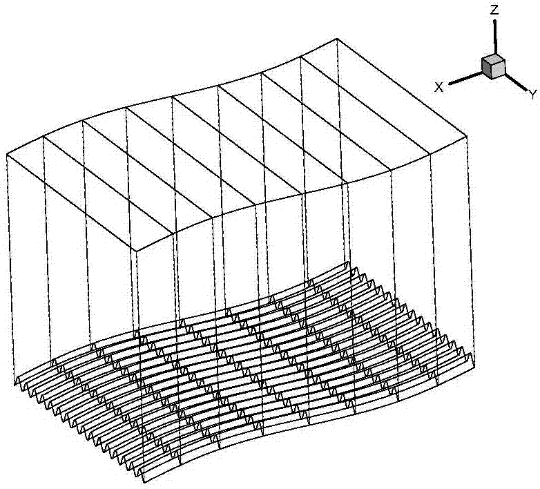
A passive heat-reduction and drag-reduction device and method for a high-velocity flow-around boundary layer. A plurality of rough belts are arranged on the surface of an aircraft to achieve passive heat reduction and drag reduction of the high-velocity flow-around boundary layer of the aircraft. Under the condition of high-velocity flows, the flow-around characteristic, near the wall surface (namely, in the area that the Mach number >= 3.5 and the distance to the wall surface <= 0.3 times the nominal thickness of a local boundary layer), of the high-velocity boundary layer is utilized to propose new principles of delayed heat transition in a laminar flow area and heat reduction and drag reduction in a turbulent flow area. The use of elliptic cylinders, quasi-prisms or rectangular columnscan produce a stable trailing vortex structure and isolated roughness elements of which the height <= 0.3 times the nominal thickness of the local boundary layer so as to achieve the functions of thedelayed transition in the laminar flow area and the heat reduction and drag reduction in the turbulent flow area. The passive heat-reduction and drag-reduction device and method for the high-velocityflow-around boundary layer can effectively reduce the energy consumption and the heat protection pressure of the aircraft and improve the endurance ability and payload of the aircraft under the condition that the flight Mach number >= 3.5 and without changing the appearance of the aircraft, applying additional energy or increasing additional equipment.

Description

technical field [0001] The invention relates to a passive heat and drag reduction device and method for high-speed flow around the boundary layer, in particular to a flow state control and fully developed turbulent zone suppression for flow around the boundary layer with a Mach number of not less than 3.5. A device for turbulent energy transport. Background technique [0002] With the development of high-speed aircraft, it is proposed to reduce the flight resistance of the aircraft, improve the ability to resist surface material damage caused by aerodynamic heating, and then achieve the requirements of widening the flight range and improving flight safety. On the one hand, in order to increase the flight distance of high-speed aircraft, it is necessary to improve the aerodynamic performance, further reduce the energy loss during its flight, and increase the lift-to-drag ratio of the aircraft. On the other hand, in order to meet the requirements of strong penetration, global...

Claims


Application Information

Patent Timeline
IPC IPC(8): B64C21/10
CPCB64C21/10Y02T50/10
Inventor 袁湘江陈星杨武兵文帅解少飞潘俊杰姚大鹏
Owner CHINA ACAD OF AEROSPACE AERODYNAMICS
Why Eureka
Try Eureka