Check patentability & draft patents in minutes with Patsnap Eureka AI!

Control signal transmission circuit and method

A technology for controlling signals and transmission methods, applied in the field of electronics, can solve the problems of complicated circuit design and control, increased circuit design bloat, multiple external working voltages, etc., to achieve the effect of simplifying the design

Inactive Publication Date: 2018-05-01
KUNSHAN GO VISIONOX OPTO ELECTRONICS CO LTD
View PDF11 Cites 1 Cited by
  • Summary
  • Abstract
  • Description
  • Claims
  • Application Information

AI Technical Summary

Problems solved by technology

However, due to the complexity of the driving principle, AMOLED requires more external operating voltage than ordinary LCD screens, resulting in more control signals at the system design end, which undoubtedly increases the bloatedness of the circuit design
In the mainstream design scheme at this stage, the first power supply voltage, the second power supply voltage and the third power supply voltage necessary for AMOLED are mainly controlled by the driver chip to enable the control terminal EN and the second control terminal SWIRE to control the external power supply chip. Obtained, the whole circuit design and control are more complicated

Method used


Image

  • Control signal transmission circuit and method
  • Control signal transmission circuit and method
  • Control signal transmission circuit and method

Examples


Embodiment Construction

[0041] The following will clearly and completely describe the technical solutions in the embodiments of the present invention with reference to the accompanying drawings in the embodiments of the present invention. Obviously, the described embodiments are only some of the embodiments of the present invention, not all of them. Based on the embodiments of the present invention, all other embodiments obtained by persons of ordinary skill in the art without making creative efforts belong to the protection scope of the present invention.

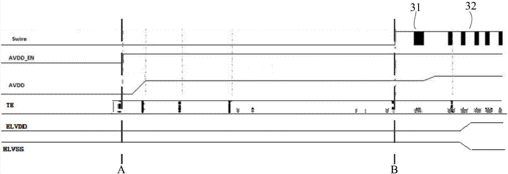
[0042] figure 1 Shown is a timing diagram of control signals and output signals of the power chip in the prior art.

[0043] Such as figure 1 As shown, in the existing technology, the first initialization command is received at time A, and the signal of the enabling control terminal EN starts to output; the second initialization command is received at time B, the second control terminal SWIRE starts to output, and SWIRE outputs a pulse 31 can c...


PUM


Abstract

The invention provides a control signal transmission circuit which comprises a driving chip, a power supply chip and a signal transmission control line connected between the signal output end of the driving chip and the control end of the power supply chip, wherein the driving chip is used for configuring a time sequence to sequentially control a plurality of power supply end output voltage valuesof the power supply chip by the signal transmission control line by way of single-line communication mode and control the control end to output a first control signal. According to the embodiment ofthe invention, an enabling control end, a second control end and one control end of the power supply chip are combined in the prior art. Based on keeping the original action of the signal transmissioncontrol line of the control end of the power supply chip, segmented electrifying control of the plurality of power supply end output voltages can be achieved in an initial stage of an AMOLED apparatus, and meanwhile, the design of the power supply chip is also simplified.

Description

technical field [0001] The invention relates to the field of electronic technology, in particular to a control signal transmission circuit and method. Background technique [0002] With the development of display technology, the application of active matrix organic light emitting diode panel (Active Matrix / Organic Light Emitting Diode, AMOLED for short), which is called the next generation display technology, is becoming more and more extensive. The light-emitting device of the AMOLED is an organic light-emitting diode (Organic Light-Emitting Diode, hereinafter referred to as OLED). Driven by the AMOLED driver chip, when a current flows through the light-emitting device OLED, the OLED emits light. However, due to the complexity of the driving principle, AMOLED requires more external operating voltage than ordinary LCD screens, resulting in the need for more control signals at the system design end, which undoubtedly increases the bloatedness of the circuit design. In the ma...

Claims


Application Information

Patent Timeline
IPC IPC(8): G09G3/3258G09G3/3291
CPCG09G3/3258G09G3/3291
Inventor 陈峰黄秀颀
Owner KUNSHAN GO VISIONOX OPTO ELECTRONICS CO LTD
Features
  • R&D
  • Intellectual Property
  • Life Sciences
  • Materials
  • Tech Scout
  • Unparalleled Data Quality
  • Higher Quality Content
  • 60% Fewer Hallucinations
Learn More