Remote monitoring system for power transmission line

A transmission line and remote monitoring technology, applied in power network operating system integration, circuit devices, emergency protection circuit devices, etc., can solve problems such as hidden safety hazards, high labor costs, electrocution, etc., and achieve the purpose of operation and maintenance. The effect of improving maintenance efficiency and avoiding potential safety hazards

Inactive Publication Date: 2018-05-01
STATE GRID CORP OF CHINA +1
View PDF6 Cites 8 Cited by
  • Summary
  • Abstract
  • Description
  • Claims
  • Application Information

AI Technical Summary

Problems solved by technology

[0002] The transmission line is one of the most important equipment in the power grid. The transmission line is affected by the environment during operation, and it is prone to short circuit, current jump, and circuit breaker. In the prior art, after the above-mentioned faults occur on the transmission line, Generally rely on staff to carry out line inspection, this method is very inefficient, and the labor cost is high, it is inconvenient for mountainous areas, it is difficult to do detailed inspections, and accidents are prone to occur; more importantly, when determining the power transmission After a line failure, if it is not possible to accurately determine whether the current state of the transmission line is live during maintenance, it will cause serious safety hazards to the staff, and even cause electric shock accidents

Method used


Image

  • Remote monitoring system for power transmission line
  • Remote monitoring system for power transmission line
  • Remote monitoring system for power transmission line

Examples


Embodiment Construction

[0021] Below in conjunction with accompanying drawing, the present invention is described in further detail:

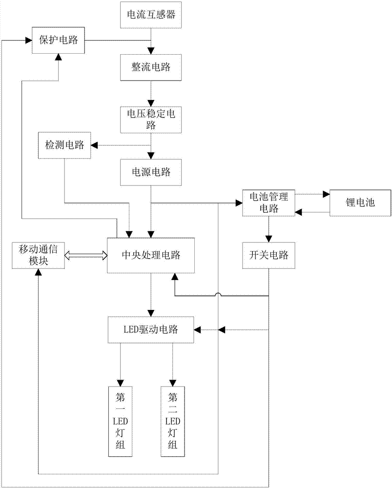
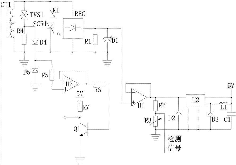
[0022] A transmission line remote monitoring system provided by the present invention includes a current transformer CT1, a rectification circuit REC, a voltage stabilization circuit, a power supply circuit, a detection circuit, a central processing circuit, a storage battery module, an LED drive circuit, a first LED lamp group and a second LED lamp group. Two LED lights;

[0023] The current transformer CT1 is arranged on the transmission line and its output end is connected to the input end of the rectification circuit REC, the output end of the rectification circuit REC is connected to the input end of the voltage stabilization circuit, and the output end of the voltage stabilization circuit is connected to the power supply The input end of the circuit is connected, the power supply circuit outputs 5V direct current and provides it to the central processing circuit...


PUM


Abstract

The invention provides a remote monitoring system for a power transmission line, and the system comprises a current transformer CT1, a rectification circuit REC, a voltage stabilizing circuit, a powercircuit, a detection circuit, a central processing circuit, a storage battery module, an LED drive circuit, a first LED lamp group, and a second LED lamp group. The system also comprises a protectioncircuit which is used for detecting the secondary side open-circuit of the current transformer and carrying out the protection, and a protection execution control end of the protection circuit is connected with the central processing circuit. The system can achieve the accurate detection of the electrification state of the power transmission line, can give a corresponding instruction according tothe electrification state, and can give an alarm timely, thereby effectively improving the confirmation efficiency of an accident point. The system is high in operation and maintenance purposiveness,improves the maintenance efficiency, can reduce the manpower cost, and avoids the safety hidden troubles in the line patrol and maintenance process. Moreover, the system has the self-detection and protection functions, and guarantees the continuous stable operation.

Description

technical field [0001] The invention relates to electric power monitoring equipment, in particular to a remote monitoring system for power transmission lines. Background technique [0002] The transmission line is one of the most important equipment in the power grid. The transmission line is affected by the environment during operation, and it is prone to short circuit, current jump, and circuit breaker. In the prior art, after the above-mentioned faults occur on the transmission line, Generally rely on staff to carry out line inspection, this method is very inefficient, and the labor cost is high, it is inconvenient for mountainous areas, it is difficult to do detailed inspections, and accidents are prone to occur; more importantly, when determining the power transmission After the line failure, if the current status of the transmission line cannot be accurately determined whether it is live during maintenance, it will cause serious safety hazards to the staff, and even ca...

Claims


Application Information

Patent Timeline
Patent Type & Authority Applications(China)
IPC IPC(8): H02H7/04H02H9/04H02J9/06H02J13/00
CPCH02J13/0006H02H7/042H02H9/043H02J9/06Y02B70/30Y02B90/20Y04S20/12Y04S20/248
Inventor 邹平彭子耀罗建平梁科田勇
Owner STATE GRID CORP OF CHINA
Why Eureka
Try Eureka