Multi-stage waste gas absorption treatment device
A treatment device and exhaust gas technology, applied in transportation and packaging, dispersed particle filtration, dispersed particle separation, etc., can solve the problem of low adsorption efficiency and achieve the effect of reasonable structure and high efficiency
- Summary
- Abstract
- Description
- Claims
- Application Information
AI Technical Summary
Problems solved by technology
Method used
Image

Examples
Embodiment Construction
[0017] The following will clearly and completely describe the technical solutions in the embodiments of the present invention with reference to the accompanying drawings in the embodiments of the present invention. Obviously, the described embodiments are only some, not all, embodiments of the present invention.
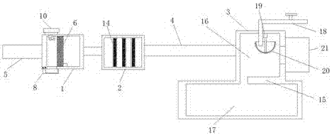
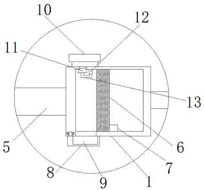
[0018] refer to Figure 1-2 , a multi-stage exhaust gas absorption treatment device, comprising a first treatment chamber 1, a second treatment chamber 2 and a third treatment chamber 3, and the first treatment chamber 1, the second treatment chamber 2 and the third treatment chamber 3 are all fixed Connected with connecting pipe 4, one side of the first processing chamber 1 is fixedly equipped with an air intake pipe 5, and a vertically arranged dust filter screen 6 is fixedly installed in the first processing chamber 1, and fixed on the bottom inner wall of the first processing chamber 1. A vibrator 7 is installed, and the vibrator 7 is in contact with the dust rem...
PUM
 Abstract
Description
Claims
Application Information
PatSnap Eureka turns technology decisions into work you can execute. Powered by our Innovation Knowledge Graph, it runs expert workflows across engineering, life sciences, materials and intellectual property. Get your review-ready output in minutes.


