Chemical raw material stirring and drying device

A technology for drying devices and chemical raw materials, which is applied in mixer parts, transportation and packaging, chemical instruments and methods, etc., can solve the problems of chemical raw materials being prone to moisture deterioration, insufficient stirring, and exceeding the index, so as to improve the stirring and mixing efficiency, improve the Mixing efficiency, convenient and fast discharge

Inactive Publication Date: 2018-05-04
长沙德科投资管理咨询有限公司
4 Cites 18 Cited by

AI-Extracted Technical Summary

Problems solved by technology

[0003] Existing chemical raw materials are various, and they need to be stirred while being used. The existing stirring devices are not sufficiently stirred, and the efficiency is ...

Method used

Principle of work of the present invention is: the present invention in use, at first chemical raw material is added in the mixing box 21 by feed hopper 14, then closes the valve on the feed hopper 14, starts first motor 24 and the second motor 16. The first motor 24 drives the stirring shaft 23 to rotate. The stirring shaft 23 drives the stirring rod 22 to rotate. The motor 16 rotates forward and backward, and the second motor 16 drives two threaded rods 11 forward and reverse through the cooperation of the pulley 17 and the belt 13. The threaded rod 11 moves up and down through the movable block 18, and the movable block 18 drives the stirring box 21 to move up and down through the hollow rotating shaft 19 At the same time, the gear 20 is meshed with the rack 12 to make the mixing box 21 move up and down while forward and reverse, so that the chemical raw materials in the mixing box 21 are constantly turned, and the mixing efficiency is further improved. When the movable block 18 moves up and down, , through the T-shaped rod 5 to drive the piston 4 to move up and down, when stirring, the air heated by the heating equipment is sucked into the cylinder body 3, and t...

Abstract

The invention discloses a chemical raw material stirring and drying device. The chemical raw material stirring and drying device comprises a bottom plate, a stirring box, a first motor, a stirring shaft, a stirring rod, a hollow rotary shaft, a movable block, a thread rod, a second motor, a belt wheel, a belt, a gear, a rack, a T-shaped rod, a piston, a cylinder body, a first pipeline, a gas inletpipe, a second pipeline and a spraying nozzle. According to the chemical raw material stirring and drying device disclosed by the invention, the first motor, the second motor, the stirring shaft, thestirring rod, the belt wheel, the belt, the movable block, the thread rod, the hollow rotary shaft, the gear, the rack and the stirring rod are arranged in a staggered manner, so that a stirring region is enlarged; when the stirring box moves up and down, the stirring box rotates frontward and backward, so that chemical raw materials in the stirring box are continuously overturned; furthermore, the stirring and mixing efficiency is improved; the T-shaped rod, the piston, the cylinder body, the water tank and the spraying nozzle are arranged so that continuous gas-spraying drying is realized and the drying efficiency is improved; the inner part of the stirring box also can be washed so that a phenomenon that the chemical raw materials are used for a long period so that the stirring box iscorroded and the service life of the stirring box is influenced is avoided.

Application Domain

Technology Topic

Image

  • Chemical raw material stirring and drying device
  • Chemical raw material stirring and drying device
  • Chemical raw material stirring and drying device

Examples

  • Experimental program(1)

Example Embodiment

[0016] The technical solutions in the embodiments of the present invention will be clearly and completely described below in conjunction with the accompanying drawings in the embodiments of the present invention. Obviously, the described embodiments are only a part of the embodiments of the present invention, rather than all the embodiments. Based on the embodiments of the present invention, all other embodiments obtained by those of ordinary skill in the art without creative work shall fall within the protection scope of the present invention.
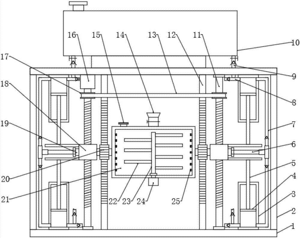
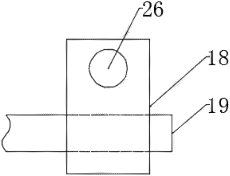
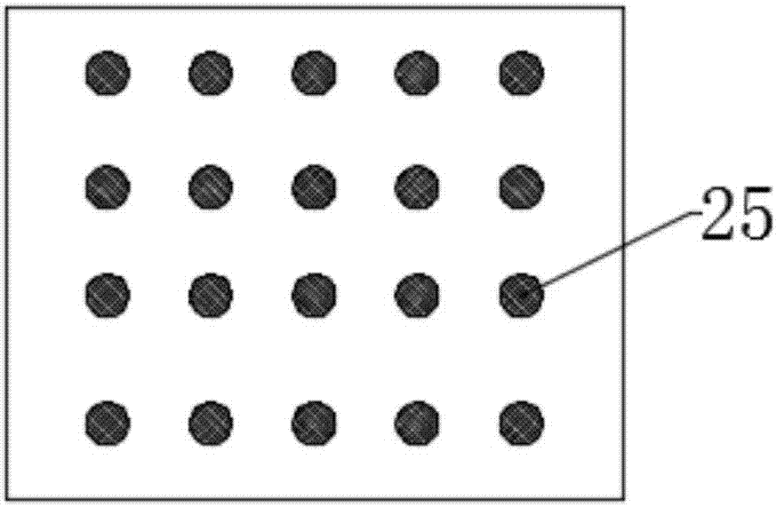
[0017] See Figure 1~3 In the embodiment of the present invention, a chemical raw material stirring and drying device includes a bottom plate 1 and a mixing box 21. The bottom plate 1 is fixed with a support plate 2 on both sides of the upper surface, and the top of the support plate 2 is fixed with a top plate. There is a mixing box 21, the top of the mixing box 21 is fixed with a feeding hopper 14 in the middle, the lower part of the feeding hopper 14 is provided with a valve, the upper left of the mixing box 21 is provided with an exhaust port, the top of the exhaust port is threaded with an end cover, and the top of the end cover The wall is composed of a filter screen. A first motor 24 is installed in the middle of the bottom of the stirring box 21. The output shaft of the first motor 24 is connected to the stirring shaft 23 through a coupling. A plurality of stirring shafts are fixed on both sides of the stirring shaft 23 at equal intervals. The rod 22 and the stirring rod 22 on both sides of the stirring shaft 23 are arranged in a staggered manner. The hollow rotating shaft 19 is fixed between the two side walls of the stirring box 21. The other end of the hollow rotating shaft 19 penetrates the movable block 18 and is rotatably connected with the movable block 18 through a bearing. The rear part is provided with a through hole 26. A threaded rod 11 is inserted through the through hole 26. The threaded rod 11 is threadedly connected with the through hole 26. The upper and lower ends of the threaded rod 11 on the right side of the mixing box 21 are rotated through the bearing seat and the top and bottom plates 1 respectively. The bottom end of the threaded rod 11 on the left side of the mixing box 21 is rotatably connected to the bottom plate 1 through a bearing seat, and the top end is connected to the output shaft of the second motor 16 through a coupling. The second motor 16 is installed at the bottom of the top plate. Two threaded rods The upper part of 11 is equipped with a belt pulley 7, and the two belt pulleys 7 are connected by a belt 13. The hollow shaft 19 is located between the movable block 18 and the side wall of the mixing box 21. A gear 20 is installed on the shaft section, and a rack is provided behind the gear 20 12. The rack 12 meshes with the gear 20, the upper and lower ends of the rack 12 are fixedly connected to the top plate and the bottom plate 1, respectively, and the first motor 24 and the second motor 16 are activated. The first motor 24 drives the stirring shaft 23 to rotate, and the stirring shaft 23 drives The stirring rod 22 rotates and the stirring rods 22 on both sides are arranged in a staggered manner, which increases the stirring area, makes the stirring more fully, and improves the stirring efficiency. At the same time, the second motor 16 is controlled to rotate forward and backward, and the second motor 16 passes through the pulley 17 and the belt 13 The two threaded rods 11 are matched to drive the forward and reverse rotations. The threaded rod 11 moves up and down through the movable block 18. The movable block 18 drives the mixing box 21 up and down through the hollow rotating shaft 19, and at the same time, the mixing box 21 is moved up and down through the meshing of the gear 20 and the rack 12 At the same time, the chemical raw materials in the mixing box 21 are constantly turned over, which further improves the mixing efficiency. The upper and lower parts of the movable block 18 away from the mixing box 21 are fixed with T-shaped rods 5, T-shaped The end of the vertical rod of the rod 5 passes through the side wall of the cylinder 3 and is fixedly connected to the piston 4. The cylinders 3 on the upper and lower sides of the movable block 18 are respectively fixed on the top plate and the bottom plate 1, and one side of the cylinder 3 is connected with the first A pipe 7, the first pipe 7 on the two cylinders 3 on the same side of the mixing box 21 is connected to the main pipe 6 through a three-way joint. The other end of the main pipe 6 is inserted into the hollow shaft 19, and the main pipe 6 passes through a bearing Rotatingly connected with the hollow shaft 19, the other side of the cylinder block 3 is connected with an intake pipe 8, the other end of the intake pipe 8 is connected with the heating device, the intake pipe 8 is connected with a second pipe 9, the second pipe The other end of the channel 9 is connected to the water tank 10. The first pipe 7, the air inlet pipe 8 and the second pipe 9 are all provided with one-way valves. The second pipe 9 and the water tank 10 are connected with a valve, and the water tank 10 is fixed by a mounting seat On the top plate 1, the upper left part of the water tank 10 is provided with a water replenishment port, the two side walls of the mixing box 21 are provided with channels, the inner cavity of the hollow rotating shaft 19 is connected with the channels, and the inner walls of the two sides of the mixing box 21 are provided with nozzles 25. There is a filter screen inside, and the nozzle 25 communicates with the channel. When the movable block 18 moves up and down, the piston 4 is driven up and down by the T-shaped rod 5. When stirring, the air heated by the heating device is sucked into the cylinder 3. Then it is pressed into the first pipe 7 from the cylinder 3, and sprayed from the nozzle 25 after passing through the main pipe 6, the hollow shaft 19 and the passage. The nozzles 25 on both sides of the mixing box 21 spray hot air at the same time to dry the chemical raw materials. To avoid excessive moisture content, the chemical raw materials cannot be used normally. Through the cooperation of multiple cylinders 3, continuous air-jet drying is realized, and the drying efficiency is improved. After the mixing and drying are completed, the mixing box 21 is moved until the hopper 14 is facing downwards. A motor 24 and a second motor 16 open the valve on the feed hopper 14 to discharge the raw materials, which is convenient and fast to discharge. Then start the first motor 24 and the second motor 16 again to open the valve on the second pipe 9 to make The water in the water tank 10 enters the cylinder body 3, and is then pressed into the first pipe 7, and then sprayed from the nozzle 25 to clean the interior of the mixing box 21 to avoid long-term use of chemical raw materials to cause corrosion to the mixing box 21 and affect it. Service life.
[0018] The working principle of the present invention is: when the present invention is used, the chemical raw materials are first added to the mixing box 21 from the feed hopper 14, and then the valve on the feed hopper 14 is closed, and the first motor 24 and the second motor 16 are activated. A motor 24 drives the stirring shaft 23 to rotate, and the stirring shaft 23 drives the stirring rod 22 to rotate. The stirring rods 22 on both sides are arranged in a staggered manner, which increases the stirring area, makes the stirring more fully, and improves the stirring efficiency. At the same time, the second motor 16 is controlled to be positive. In reverse, the second motor 16 drives the two threaded rods 11 to move forward and backward through the pulley 17 and the belt 13, the threaded rod 11 moves up and down through the movable block 18, and the movable block 18 drives the mixing box 21 up and down through the hollow rotating shaft 19, and passes The gear 20 meshes with the rack 12 to make the mixing box 21 move forward and backward while moving up and down, so that the chemical raw materials in the mixing box 21 are constantly flipped, and the mixing efficiency is further improved. The movable block 18 moves up and down while passing the T The rod 5 drives the piston 4 to move up and down. When stirring, the air heated by the heating device is sucked into the cylinder 3, and then pressed from the cylinder 3 into the first pipe 7, through the main pipe 6, the hollow shaft 19 and the passage Then it is sprayed from the nozzle 25, and the nozzles 25 on both sides of the mixing box 21 spray hot air at the same time to dry the chemical raw materials to prevent the chemical raw materials from being unable to be used normally due to excessive moisture. The multiple cylinders 3 work together to achieve continuous jet drying. The drying efficiency is improved. After the mixing and drying are completed, the mixing box 21 is moved to the hopper 14 downwards, the first motor 24 and the second motor 16 are closed, the valve on the hopper 14 is opened, the raw materials are discharged, and the material is discharged Convenient and fast, and then start the first motor 24 and the second motor 16 again, open the valve on the second pipe 9, so that the water in the water tank 10 enters the cylinder 3, and then is pressed into the first pipe 7, and then by the nozzle 25 spray out, clean the inside of the mixing box 21 to avoid long-term use of chemical raw materials to cause corrosion to the mixing box 21 and affect its service life.
[0019] For those skilled in the art, it is obvious that the present invention is not limited to the details of the foregoing exemplary embodiments, and the present invention can be implemented in other specific forms without departing from the spirit or basic characteristics of the present invention. Therefore, from any point of view, the embodiments should be regarded as exemplary and non-limiting. The scope of the present invention is defined by the appended claims rather than the foregoing description, and therefore it is intended to fall within the claims. All changes within the meaning and scope of equivalent elements of are included in the present invention. Any reference signs in the claims should not be regarded as limiting the claims involved.
[0020] In addition, it should be understood that although this specification is described in accordance with the implementation manners, not each implementation manner only includes an independent technical solution. This narration in the specification is only for clarity, and those skilled in the art should consider the specification as a whole The technical solutions in the embodiments can also be appropriately combined to form other implementations that can be understood by those skilled in the art.

PUM

no PUM

Description & Claims & Application Information

We can also present the details of the Description, Claims and Application information to help users get a comprehensive understanding of the technical details of the patent, such as background art, summary of invention, brief description of drawings, description of embodiments, and other original content. On the other hand, users can also determine the specific scope of protection of the technology through the list of claims; as well as understand the changes in the life cycle of the technology with the presentation of the patent timeline. Login to view more.

Similar technology patents

Device and method for homogenizing high-temperature melt

InactiveCN102698634AStirring power is smallIncrease the stirring areaRotary stirring mixersTransportation and packagingSlagHeating system
Owner:ANHUI UNIVERSITY OF TECHNOLOGY

Novel concrete mixer

InactiveCN106626064AAvoid underfill or wasteStir wellCement mixing apparatusDrive motorEngineering
Owner:唐健发 +1

Classification and recommendation of technical efficacy words

  • Increase the stirring area
  • Stir well

Device and method for homogenizing high-temperature melt

InactiveCN102698634AStirring power is smallIncrease the stirring areaRotary stirring mixersTransportation and packagingSlagHeating system
Owner:ANHUI UNIVERSITY OF TECHNOLOGY

Simulation test device for debris flow and test method

PendingCN106841573AStir wellAdjustable inclinationEarth material testingHydraulic ramLift system
Owner:NORTHWEST RES INST CO LTD OF C R E C
Why Eureka
Try Eureka