Two-way pressure compensation valve

A pressure compensation and valve core technology, applied in the field of two-way pressure compensation valve, can solve the problems of simple damping, unsatisfactory buffering of load pressure fluctuations, large volume, etc., to achieve good buffering of load pressure fluctuations, convenient application and promotion, and simple circuit structure Effect

Active Publication Date: 2019-12-24
江苏广瀚非开挖管道技术有限公司
View PDF7 Cites 0 Cited by
  • Summary
  • Abstract
  • Description
  • Claims
  • Application Information

AI Technical Summary

Problems solved by technology

[0003] In actual application conditions, since the load pressure fluctuates from time to time, it will cause the opening of the feedback spool to fluctuate, which will cause the jitter of the actuator; Damping is added between the load feedback chambers of the valve core. For example, the invention patent with the publication number "CN 101922477" and the name "Pressure Compensation Valve" discloses a superimposed pressure compensation valve, which adds a first damper to the load pressure feedback chamber. However, because the damping is too simple, it is not ideal for buffering load pressure fluctuations, and because the pressure compensation valve is superimposed and bulky, it is not conducive to the application in the field of construction machinery

Method used


Image

  • Two-way pressure compensation valve
  • Two-way pressure compensation valve
  • Two-way pressure compensation valve

Examples


Embodiment Construction

[0025] In order to make the technical solutions and advantages of the present invention clearer, the exemplary embodiments of the present invention will be further described in detail below in conjunction with the accompanying drawings. Apparently, the described embodiments are only a part of the embodiments of the present invention, and are not exhaustive of all the embodiments. And in the case of no conflict, the embodiments and the features in the embodiments of the present invention can be combined with each other.

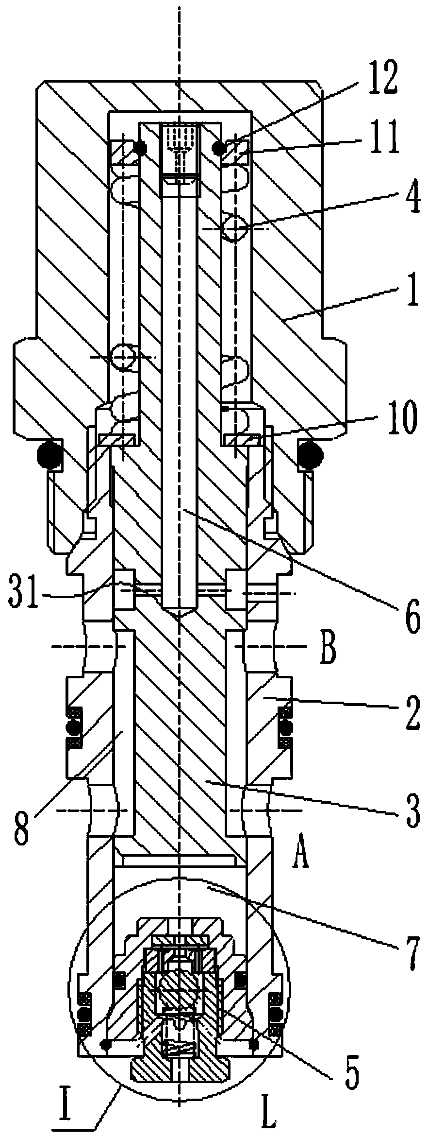
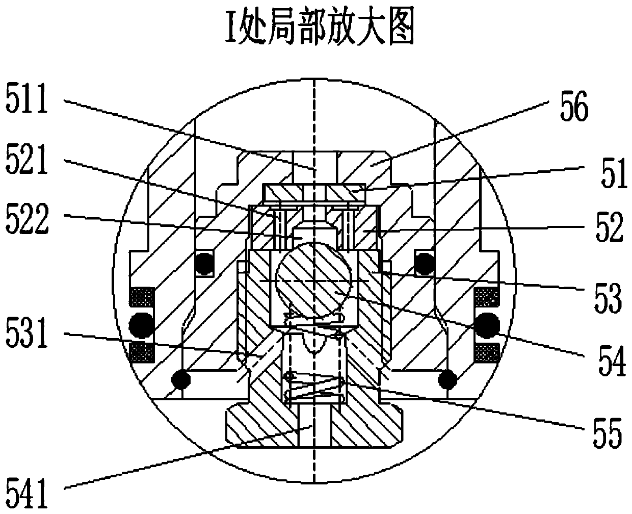
[0026] Such as figure 1 One of the embodiments of the two-way pressure compensating valve of the present invention is shown. In this embodiment, the two-way pressure compensation valve of the present invention mainly includes: a screw sleeve 1 , a valve sleeve 2 , a valve core 3 , a spring 4 , and a damping valve assembly 5 . Wherein, the valve sleeve 2 is provided with axial L port and radial A port and B port sequentially from bottom to top. The spool 3 i...


PUM


Abstract

The invention provides a two-way pressure-compensated valve. The two-way pressure-compensated valve comprises a valve bush, a valve core, a thread sleeve, a spring and a damping valve assembly. The valve bush is provided with a port A, a port B and a port L. The valve core is arranged in the valve bush, a first flowing channel is formed in one end of the valve core, and the first flowing channel communicates with the port B. The thread sleeve is connected to the end, close to the first flowing channel, of the valve bush. The spring is located in an inner cavity of the thread sleeve, the lowerportion of the spring is connected to the upper end of the valve bush through a first gasket in a pressing mode, and the other end of the spring abuts against the valve core through a second gasket and a stop ring. The damping valve assembly is fixedly connected to the lower end of the valve bush, and a load feedback cavity is formed above the damping valve assembly. A first damping channel and asecond damping channel connected with the load feedback cavity and the port L are formed in the damping valve assembly, and damping of the second damping channel is higher than that of the first damping channel. The situation that the damping magnitude of oil fluid flowing in and out of the load feedback cavity is different is achieved through the damping valve assembly, thus influences of loadingpressure punctuation on the ports of the valve core are buffered, and rapid response is achieved. The two-way pressure-compensated valve is compact in structure, and can effectively buffer load feedback pressure punctuation while not affecting the response speed.

Description

technical field [0001] The invention relates to the technical field of pressure compensation valves, in particular to a two-way pressure compensation valve used in load sensitive systems of engineering machinery such as wheel loaders, cranes, and small excavators. Background technique [0002] Quantitative load sensing system is widely used in engineering machinery such as loaders, truck cranes and small excavators because of its energy saving and low cost. The load-sensing multi-way reversing valve is the core component of this type of load-sensing system, and the quantitative load-sensing system needs to realize the on-demand distribution of actuator flow, and the two-way pressure compensation valve is an indispensable component of this type of hydraulic control system. In the existing two-way pressure compensation valve, one end of the spool communicates with the oil inlet chamber of the valve body, and the other end communicates with the load feedback pressure oil. The ...

Claims


Application Information

Patent Timeline
Patent Type & Authority Patents(China)
IPC IPC(8): F15B13/02F16K3/26
CPCF15B13/026F16K3/262
Inventor 陈艳艳
Owner 江苏广瀚非开挖管道技术有限公司
Why Eureka
Try Eureka