Bevel gear ultrasonic automatic detection device and method

An automatic detection device and technology of detection device, which are applied in measurement devices, analysis of solids using sonic/ultrasonic/infrasonic waves, and material analysis using sonic/ultrasonic/infrasonic waves, etc., can solve the problems of low detection efficiency, detection error, complicated operation, etc. , to achieve the effect of high detection efficiency, accurate vertical positioning and wide applicability

Pending Publication Date: 2018-05-04
CHINA THREE GORGES UNIV
View PDF7 Cites 20 Cited by
  • Summary
  • Abstract
  • Description
  • Claims
  • Application Information

AI Technical Summary

Problems solved by technology

The current non-destructive testing technology is generally manual testing, using manual hand-held probes, and the need to apply coupling agent, the operation is complicated, and it is easy to be affected by human factors to cause detection errors, and its detection efficiency is very low

Method used


Image

  • Bevel gear ultrasonic automatic detection device and method
  • Bevel gear ultrasonic automatic detection device and method
  • Bevel gear ultrasonic automatic detection device and method

Examples


Embodiment 1

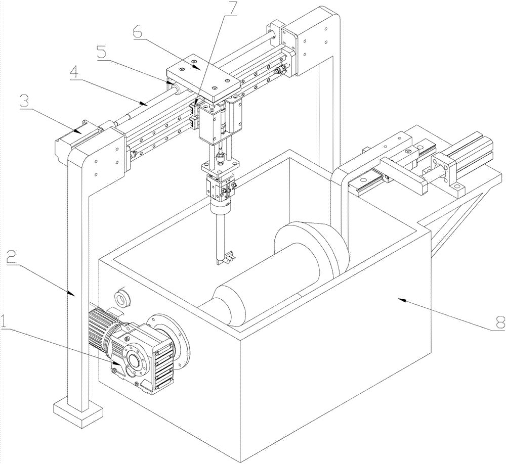
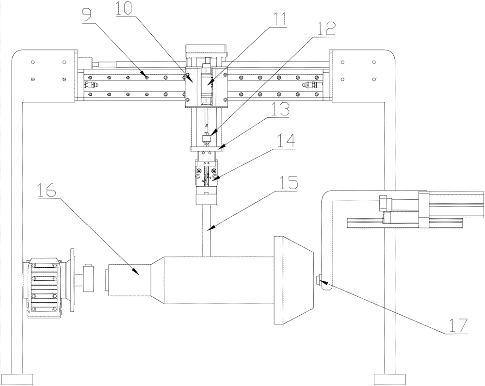
[0035] see Figure 1-4 , an ultrasonic automatic detection device for bevel gears, which includes a positioning and rotating device for bevel gear positioning, a sliding device is fixedly installed above the positioning and rotating device through a support frame 2, and a connecting plate 13 below the sliding device A testing device for ultrasonic testing is installed. The device can realize the ultrasonic automatic detection of bevel gears. The device uses layered array longitudinal wave straight probes to detect flaws from the surface of the workpiece, and uses probes with different frequencies to detect different depths of the workpiece. It can accurately and effectively detect internal defects of the workpiece, and the detection efficiency is higher. High and suitable for bevel gear testing of various specifications.

[0036] Further, the workpiece positioning and rotating device includes a water tank 8, a motor 1 is fixedly installed on the left outer wall of the water t...

Embodiment 2

[0043] The detection method of any described bevel gear ultrasonic automatic detection device, it comprises the following steps:

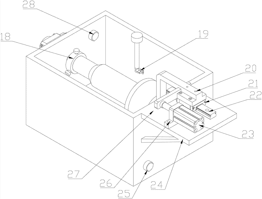
[0044] Step1: According to the size of the bevel gear 16 to be detected, select an array probe 19 of a suitable model, install it on the probe fixture at the end of the probe bracket 15, and connect the probe to the ultrasonic detector;

[0045] Step2: Install the shaft end of the bevel gear 16 to be tested on the three-jaw chuck 18, and tighten the three-jaw chuck 18 to clamp and position the shaft end;

[0046] Step3: push the cylinder 23 to drive the positioning device, drive the head bracket 20 to move, and tighten the head 17 to the end face of the bevel gear 16 to be tested, and complete the clamping and positioning of the bevel gear 16 to be tested;

[0047] Step4: After the bevel gear 16 to be detected is positioned, fill water into the water tank 8 through the water inlet 28, and when the water is full, drive the bevel gear to rotate throu...


PUM


Abstract

The invention discloses a bevel gear ultrasonic automatic detection device and a bevel gear ultrasonic automatic detection method. The bevel gear ultrasonic automatic detection device comprises a workpiece rotating positioning device; the axis of a bevel gear can be positioned by a three-claw chuck; a pushing cylinder drives a push head to move to realize positioning and clamping of the bevel gear; a motor drives the three-claw chuck to rotate to realize rotation of the bevel gear; a sliding device is fixedly arranged above the positioning rotating device through a supporting frame; and a detection device for ultrasonic detection is arranged on a connecting plate below the sliding device. By adoption of the bevel gear ultrasonic automatic detection device, ultrasonic automatic detection ofthe bevel gear can be realized; the device adopts a layered array longitudinal wave straight probe to perform flaw detection on the surface of a workpiece, utilizes probes with different frequency todetect different depths of the work piece, can detect the internal defects of the workpiece accurately and effectively, can realize workpiece all-region coverage detection through rotation of the workpiece and movement of the probe, and has high detection efficiency.

Description

technical field [0001] The invention relates to an ultrasonic testing device, in particular to a bevel gear ultrasonic automatic testing device and method, belonging to the field of ultrasonic nondestructive testing. Background technique [0002] With the development of social technology and productivity, people have higher and higher requirements for the quality of materials, among which the quality inspection of transmission parts and key parts is particularly important. After the bevel gear blank is forged, defects such as cracks, folds, white spots, shrinkage cavities, and inclusions are prone to appear inside the part. The traditional detection method needs to destroy the workpiece, and the detection is difficult. The current non-destructive testing technology is generally manual testing, which uses manual hand-held probes and requires smearing of couplant. The operation is complicated, and it is easily affected by human factors to cause detection errors, and its detect...

Claims


Application Information

Patent Timeline
Patent Type & Authority Applications(China)
IPC IPC(8): G01N29/04G01N29/22
CPCG01N29/04G01N29/225G01N2291/2693G01N2291/0289
Inventor 关山月
Owner CHINA THREE GORGES UNIV
Why Eureka
Try Eureka