
Electrochromic device capable of independently controlling electrochromic layers

A technology of electrochromic devices and electrochromic layers, applied in instruments, nonlinear optics, optics, etc., can solve the problems of fading and discoloration of electrochromic layers, and the inability of a single electrochromic layer to be colored independently

Inactive Publication Date: 2018-05-04
姜卫东
View PDF6 Cites 2 Cited by
  • Summary
  • Abstract
  • Description
  • Claims
  • Application Information

AI Technical Summary

Problems solved by technology

[0003] The existing "substrate ─ electrode layer ─ electrochromic layer ─ electrolyte layer ─ electrochromic layer ─ electrode layer ─ substrate" structure electrochromic device, when the two electrochromic layers are both cathode electrochromic When the color-changing layer or the same is an anode electrochromic layer, connecting the electrode layers on both sides to the positive and negative poles of the DC power supply can only make one electrochromic layer color and the other electrochromic layer fade, but it cannot make the two electrochromic layers fade. Both electrochromic layers are faded; when the two electrochromic layers are the cathode electrochromic layer and the anode electrochromic layer respectively, the electrode layers on both sides are respectively connected to the positive and negative poles of the DC power supply at the same time, only two Electrochromic layers color and fade simultaneously, but individual electrochromic layers cannot color and fade independently
The reason why the above-mentioned two electrochromic layers cannot both fade or a single electrochromic layer cannot be independently colored and faded is that the electrode layers on both sides are the only counter electrode layers for each other, and if the electrochromic layers on either side are to be For coloring or fading, the electrode layer on this side and the counter electrode layer on the opposite side must be connected to the positive and negative poles of the DC power supply, which will inevitably lead to discoloration of the electrochromic layer on the counter electrode layer on the opposite side.
The existence of this problem has affected the popularization and application of electrochromic technology in optics, display, security and other fields to a certain extent.

Method used


Image

  • Electrochromic device capable of independently controlling electrochromic layers
  • Electrochromic device capable of independently controlling electrochromic layers
  • Electrochromic device capable of independently controlling electrochromic layers

Examples


Embodiment 1

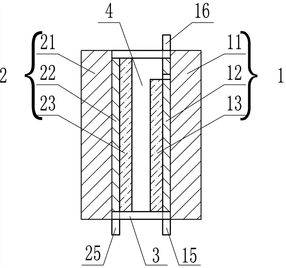
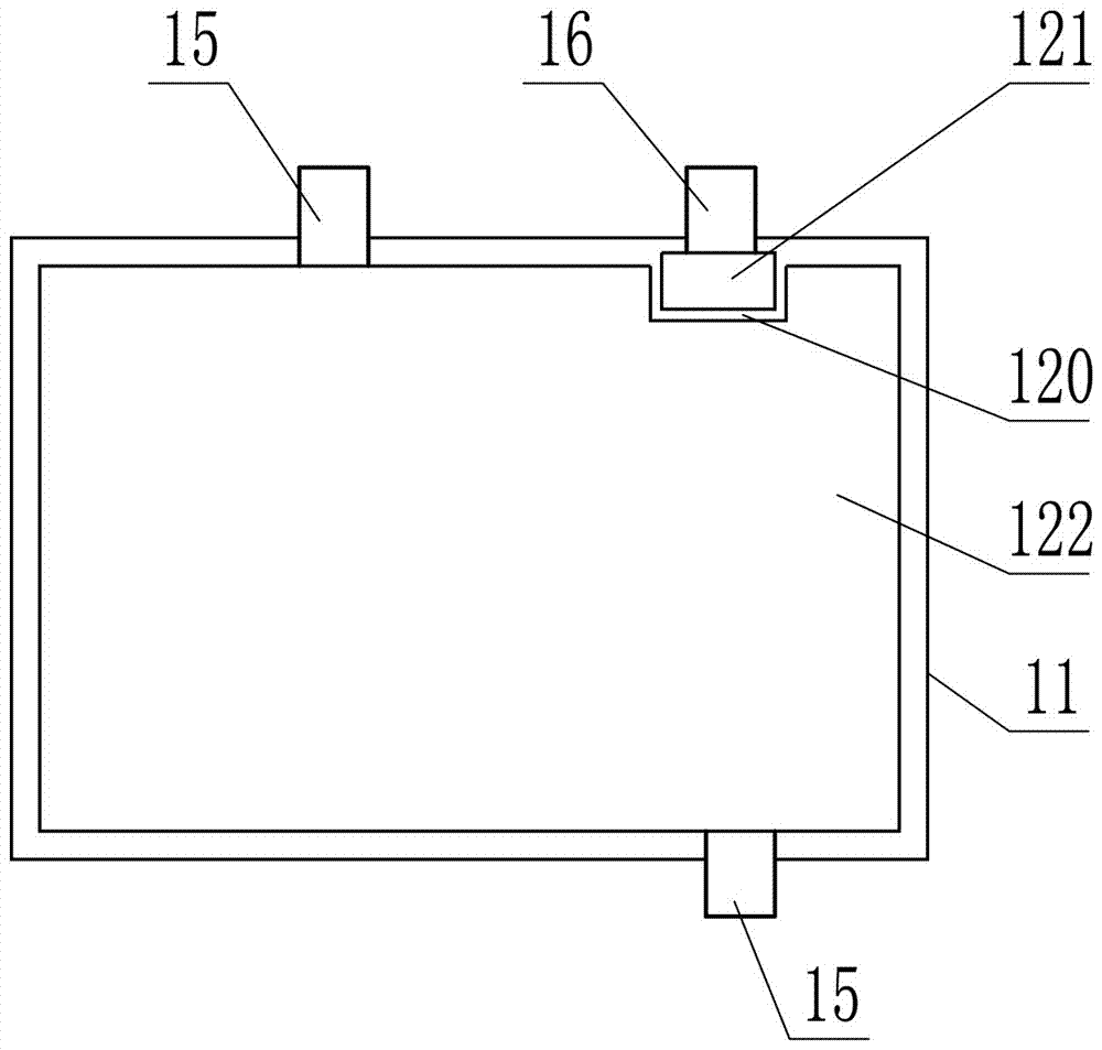
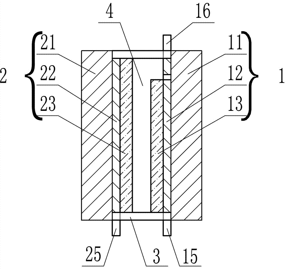
[0040] The electrochromic device that can independently control the electrochromic layer described in this embodiment, by such as figure 1 As shown, it consists of two electrode sheets covered with electrochromic layers, electrolyte layer and edge banding. Among the two electrode sheets covered with an electrochromic layer, one electrode sheet is a single-sided electrode sheet with one layer of electrodes covered with an electrochromic layer, and the other electrode sheet is a one-layer electrode sheet covered with an electrochromic layer. Electrode sheet with single area and single side. The electrochromic device with independently controllable electrochromic layers may have a planar or non-planar shape.

[0041] The one-layer electrode two-region single-sided electrode sheet covered with an electrochromic layer refers to a special electrode sheet for electrochromic devices covered with an electrochromic layer on the electrode layer on the one-layer electrode two-region sing...

Embodiment 2

[0056] The electrochromic device described in this embodiment that can independently control the electrochromic layer refers to the electrochromic device that is composed of two electrode sheets covered with an electrochromic layer, an electrolyte layer and a side seal, which can make both sides of the electrochromic layer An electrochromic device in which the color-changing layers can all fade or at least one electrochromic layer in the heteropolar electrochromic layers on both sides can change color independently. The two electrode sheets covered with an electrochromic layer are two electrode sheets with one layer of electrodes and two regions and one surface covered with an electrochromic layer. The electrochromic device with independently controllable electrochromic layers may have a planar or non-planar shape.

[0057] The single-sided electrode sheet with one layer of electrodes and two regions covered with an electrochromic layer is the same as the one-sided electrode s...


PUM

PropertyMeasurementUnit
thicknessaaaaaaaaaa

Abstract

The invention discloses an electrochromic device capable of independently controlling electrochromic layers. The electrochromic device comprises two electrode plates, an electrolyte layer and a seal edge, wherein the electrolyte layer is arranged between the two electrode plates; the seal edge is used for encapsulating the electrolyte layer; the electrode plates comprise bases, electrode layers arranged on certain sides of the bases and the electrochromic layers arranged on the outer sides of the electrode layers; the electrode layers comprise main electrode areas; the electrode layer on at least one electrode plate is also provided with an auxiliary electrode area mutually isolated from the main electrode areas; each electrode area is provided with an electrode outer leading wire which isconnected with an external power supply; the main electrode areas of the electrode layers are provided with the electrochromic layers; the electrolyte layer is arranged between the two electrode plates, and is encapsulated through a circle of the seal edge between the bases of the two electrode plates. The electrochromic device is used for solving problems that an electrochromic device with two homopolar electrochromic layers cannot be used for discoloring the two electrochromic layers and an electrochromic device with two heteropolar electrochromic layers cannot be used for independently coloring and discoloring the single electrochromic layer.

Description

technical field [0001] The invention belongs to the technical field of electrochromic devices, in particular to an electrochromic device capable of independently controlling an electrochromic layer. Background technique [0002] Electrochromism refers to the phenomenon that the optical properties such as color, transmittance, reflectivity, and absorptivity of materials undergo stable and reversible changes under the action of an external electric field, and the appearance is manifested as reversible changes in color and transparency. Materials with electrochromic properties are called electrochromic materials. Materials that color when connected to the cathode of the power supply and fade when connected to the anode of the power supply are called cathodic color-changing materials. Materials that color when connected to the anode of the power supply and fade when connected to the cathode of the power supply It is called anodic color changing material. A structure with electr...

Claims


Application Information

Patent Timeline
Patent Type & Authority Applications(China)
IPC IPC(8): G02F1/15G02F1/153G02F1/155
CPCG02F1/15G02F1/153G02F1/155
Inventor 姜卫东刘畅宋波姜金花陈洪亮
Owner 姜卫东
Learn More