
Electro-optic Q-switched solid laser

A solid-state laser and electro-optic technology, applied in the laser field, can solve the problems of increased cost and inability to achieve precision, and achieve the effect of high reliability and reduced cost

Inactive Publication Date: 2018-05-04
成都心无界光电技术有限公司
View PDF6 Cites 14 Cited by
  • Summary
  • Abstract
  • Description
  • Claims
  • Application Information

AI Technical Summary

Problems solved by technology

Laser pulses below 20ns will improve the accuracy of laser detection and laser display, which cannot be achieved by current electro-optic Q-switched lasers
In addition, the current electro-optic Q-switching driver can only work in one working mode. If you want to work in a different way, you need to replace the electro-optic Q-switching driver, which increases the cost

Method used


Image

  • Electro-optic Q-switched solid laser

Examples


Embodiment Construction

[0015] The following will clearly and completely describe the technical solutions in the embodiments of the present invention with reference to the accompanying drawings in the embodiments of the present invention. Obviously, the described embodiments are only some, not all, embodiments of the present invention. The components of the embodiments of the invention generally described and illustrated in the figures herein may be arranged and designed in a variety of different configurations. Accordingly, the following detailed description of the embodiments of the invention provided in the accompanying drawings is not intended to limit the scope of the claimed invention, but merely represents selected embodiments of the invention. Based on the embodiments of the present invention, all other embodiments obtained by those skilled in the art without making creative efforts belong to the protection scope of the present invention.

[0016] It should be noted that like numerals and let...


PUM


Abstract

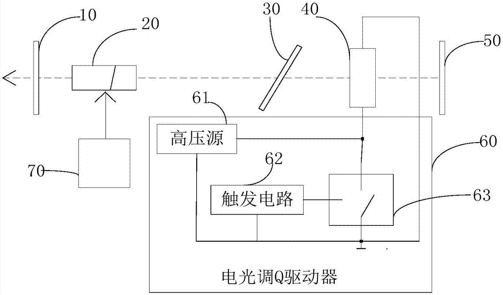
The invention relates to an electro-optic Q-switched solid laser. The electro-optic Q-switched solid laser comprises a laser resonant cavity formed by an output mirror, a laser medium and a total reflective mirror, wherein a polaroid and an electro-optic Q-switched crystal are arranged between the laser medium and the total reflective mirror sequentially, and the electro-optic Q-switched crystal is connected with an electro-optic Q-switched driver; the electro-optic Q-switched driver comprises a high-voltage source, a trigger circuit and a switch; the switch comprises a first end for being connected with one end of the electro-optic Q-switched crystal, a second end for being connected with the other end of the electro-optic Q-switched crystal and the ground and a third end for controllingon and off of the first end and the second end. According to the electro-optic Q-switched solid laser, two kinds of driving, namely, decompression or pressurization, can be realized, the output pulsewidth of laser pulses is accurate and controllable, and the output pulse width of the laser can be reduced.

Description

technical field [0001] The invention relates to the field of laser technology, in particular to an electro-optic Q-switched solid-state laser. Background technique [0002] The electro-optic Q-switching method is a technology that uses the electro-optic effect of crystals to adjust the Q value, so that the laser can output laser with high peak power and narrow pulse width. However, the pulse width of the general electro-optic Q-switched laser output is about 30ns. In laser detection and laser display, the lower the pulse width of the laser pulse, the higher the display accuracy. Laser pulses below 20ns will improve the accuracy of laser detection and laser display, which cannot be achieved by current electro-optic Q-switched lasers. In addition, the current electro-optic Q-switching driver can only work in one working mode. If a different mode is to be used, the electro-optic Q-switching driver needs to be replaced, which increases the cost. Contents of the invention ...

Claims


Application Information

Patent Timeline
IPC IPC(8): H01S3/115H01S3/16
CPCH01S3/115H01S3/1611H01S3/1643H01S3/1673
Inventor 胡育侠
Owner 成都心无界光电技术有限公司
Learn More