
Thread driving type force arm orthopedics traction device

A threaded drive and traction device technology, applied in medical science, external fixator, surgery, etc., can solve problems such as blisters, difficult to reach, nosocomial infection, etc., and achieve the effect of improving work efficiency, strong practicability, and reducing pain

Active Publication Date: 2018-05-08
尹刚
View PDF9 Cites 6 Cited by
  • Summary
  • Abstract
  • Description
  • Claims
  • Application Information

AI Technical Summary

Problems solved by technology

[0002] Now the methods of limb traction include skin traction and bone traction: skin traction is mainly used for elderly patients and children under 8 years old. Its effective traction force is small, and the skin is prone to blisters due to traction tension. Bone traction is commonly used in orthopedic clinics. However, the current clinical method is: use a hammer to drive a Kirschner wire or Steiner wire from one side of the bone, and pass through the bone marrow cavity to penetrate the opposite side skeletal muscle and skin. Patients have fear before traction, and in this method, the traction needle has to pass through the bone marrow cavity and run through the opposite side. When the traction is to be released in the future, the traction needle also has to pass through the bone marrow cavity, and it is difficult to achieve orthopedic disinfection with povidone iodine and alcohol. Sterilization requirements increase the chance of deep infection, leading to the possibility of nosocomial infection. At the same time, during the process of inserting the traction needle, the external force and vibration will cause aggravated pain at the fracture site of the affected limb, increase the pain of the patient, and even induce other diseases, such as Hypertension, Asthma, etc.
[0003] In order to solve the above problems, an orthopedic retractor is disclosed in the existing patent announcement number CN206587023U, but this device needs to be adjusted manually, and the operation is relatively cumbersome. bring more pain

Method used


Image

  • Thread driving type force arm orthopedics traction device
  • Thread driving type force arm orthopedics traction device
  • Thread driving type force arm orthopedics traction device

Examples


Embodiment Construction

[0016] The following will clearly and completely describe the technical solutions in the embodiments of the present invention with reference to the accompanying drawings in the embodiments of the present invention. Obviously, the described embodiments are only some, not all, embodiments of the present invention. Based on the embodiments of the present invention, all other embodiments obtained by persons of ordinary skill in the art without making creative efforts belong to the protection scope of the present invention.

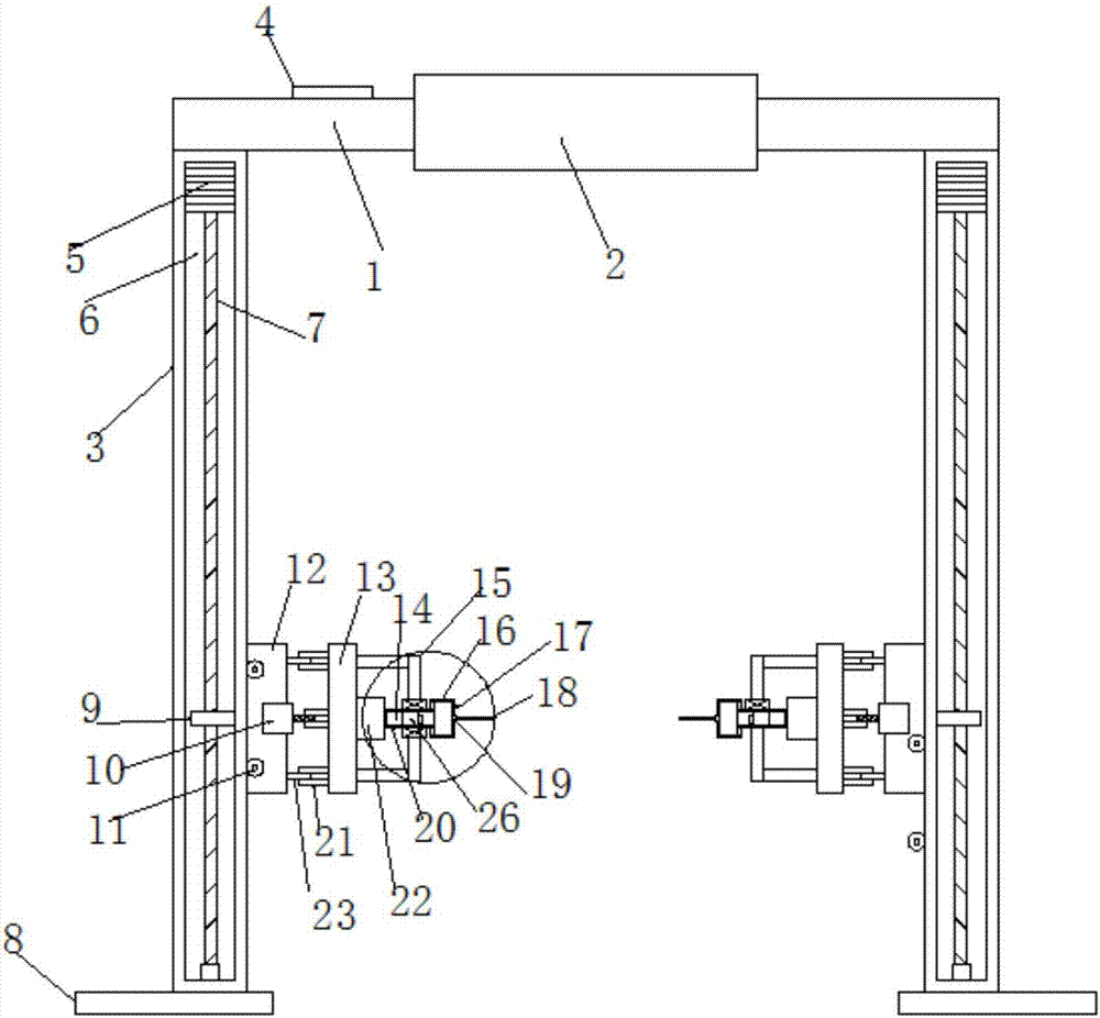
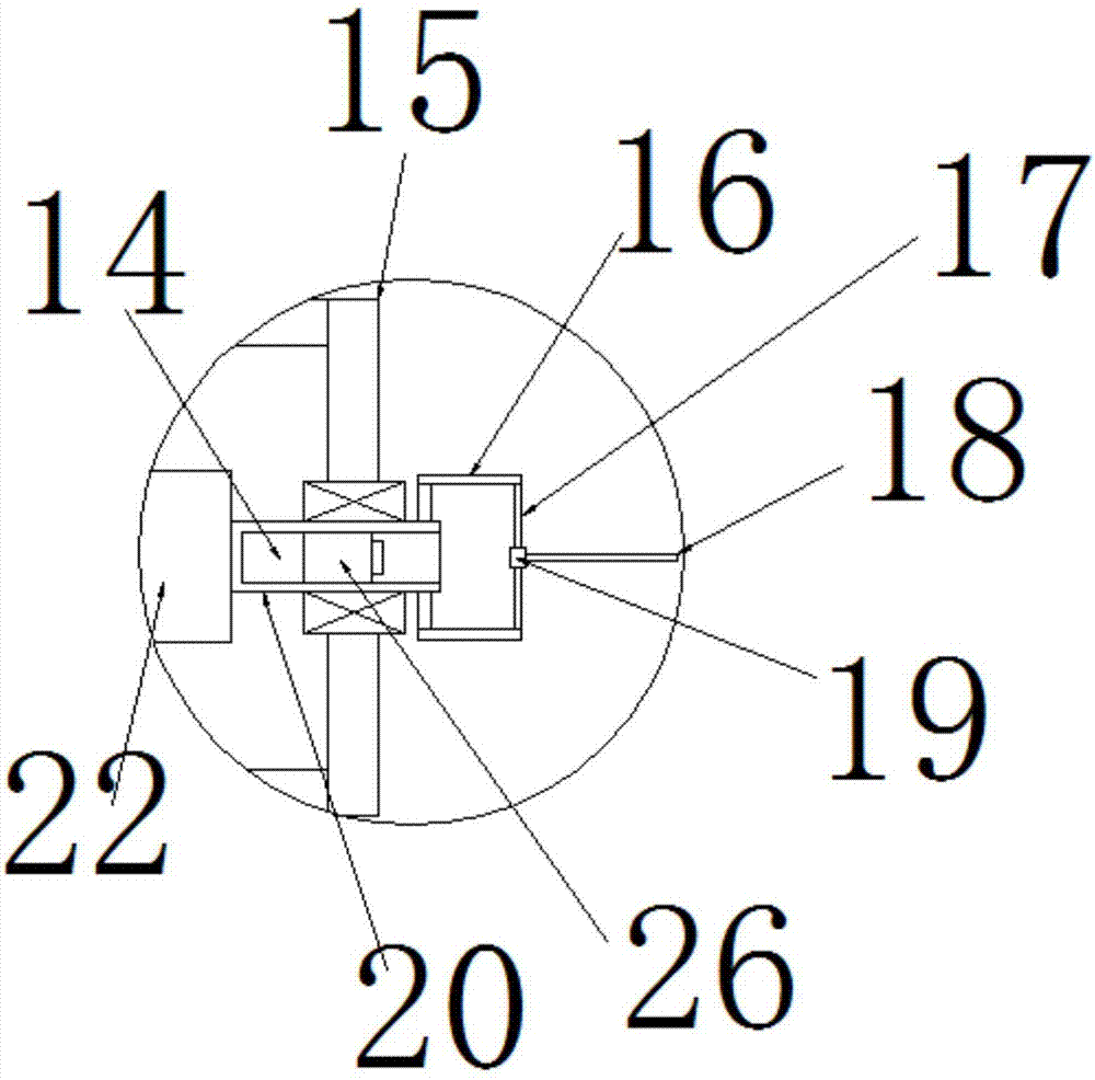
[0017] see Figure 1~3 , in an embodiment of the present invention, a screw drive type force arm orthopedic traction device includes a hand-held rod 1 and a support column 3, the middle and outer sides of the hand-held rod 1 are provided with anti-slip sleeves 2, and the left and right sides of the hand-held rod 1 are symmetrical A support column 3 is provided, and a support plate 8 is fixed at the lower end of the support column 3. The function of the support...


PUM


Abstract

The invention discloses a thread driving type force arm orthopedics traction device, which comprises a handhold rod and supporting pillars; the outside of the middle of the handhold rod is sleeved with an anti-slide sleeve, left and right sides of the handhold rod are symmetrically provided with the supporting pillars; the lower ends of the supporting pillars are fixed with supporting plates, andthe supporting plates are used for facilitating the vertical placement of the device; driving cavities are not arranged in the supporting pillars, and the inner parts of the driving cavities are vertically provided with lifting screw bars; the upper ends of the lifting screw bars are connected and fixed with the output ends of lifting motors, and the lifting motors are fixed at the top parts in the driving cavities; the lower ends of the lifting screw bars are rotationally connected with the bottom parts of the driving cavities; left and right supporting pillars are glidingly provided with lifting slide blocks towards the opposite face. The thread driving type force arm orthopedics traction device is simple and reasonable in structure, and facilitates the skeletal fixation, reduces the pain in treatment, and is good for improving the working efficiency of workers; the thread driving type force arm orthopedics traction device is strong in practicability.

Description

technical field [0001] The invention relates to the technical field of medical orthopedic equipment, in particular to a screw drive type force arm orthopedic traction device. Background technique [0002] Now the methods of limb traction include skin traction and bone traction: skin traction is mainly used for elderly patients and children under 8 years old. Its effective traction force is small, and the skin is prone to blisters due to traction tension. Bone traction is commonly used in orthopedic clinics. However, the current clinical method is: use a hammer to drive a Kirschner wire or Steiner wire from one side of the bone, and pass through the bone marrow cavity to penetrate the opposite side skeletal muscle and skin. Patients have fear before traction, and in this method, the traction needle has to pass through the bone marrow cavity and run through the opposite side. When the traction is to be released in the future, the traction needle also has to pass through the bo...

Claims


Application Information

Patent Timeline
IPC IPC(8): A61B17/66A61B17/16
CPCA61B17/1604A61B17/1628A61B17/66A61B2017/564
Inventor 金雄
Owner 尹刚
Learn More