
Device for cleaning ventilation cabinet used in metal testing room

A metal detection and cleaning device technology, which is applied to lighting devices, lighting devices, lighting device components, etc., can solve problems such as physical exertion, cross-contamination, cleaning devices and fume hood humidity, and improve cleaning efficiency and automation High, enhanced reliability effect

Pending Publication Date: 2018-05-08
JIANGSU SCIENCE TEST TECHNOLOGY SERVICE CO LTD
View PDF7 Cites 1 Cited by
  • Summary
  • Abstract
  • Description
  • Claims
  • Application Information

AI Technical Summary

Problems solved by technology

[0006] 1. The water flow rate of the cleaning device of the above invention cannot be controlled, and the faucet needs to be manually opened and closed, and the drainage is also uncontrollable, which takes physical effort and easily leads to contact cross-contamination;
[0007] 2. The cleaning device of the above invention has no lighting function, is difficult to operate at night, does not have a drying function, and is exposed in the fume hood, which easily leads to local dampness of the cleaning device and the fume hood;

Method used


Image

  • Device for cleaning ventilation cabinet used in metal testing room
  • Device for cleaning ventilation cabinet used in metal testing room

Examples


Embodiment

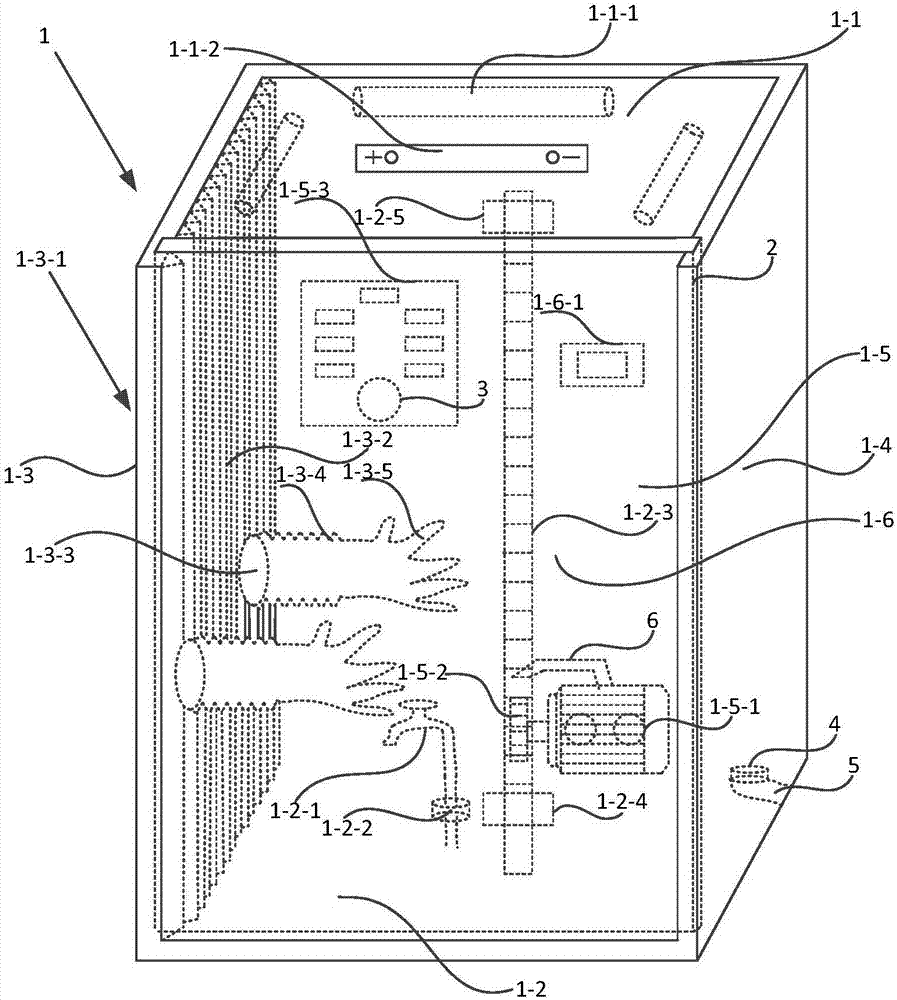
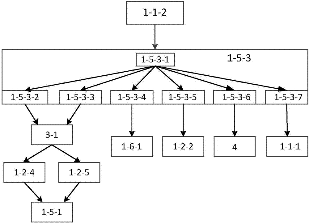
[0040] Embodiment: a kind of fume hood cleaning device for metal detection room, as Figure 1-Figure 2 As shown, a casing 1 is included, and the casing includes an upper bottom surface 1-1, a lower bottom surface 1-2, a left side wall 1-3, a right side wall 1-4, a front door 1-5 and a back side 1-6;

[0041] The inner surface of the upper bottom surface is provided with several lighting lamps 1-1-1, and the outer surface of the upper bottom surface is provided with a battery pack 1-1-2;

[0042] The lower bottom surface is fixed with a water supply device and a drainage solenoid valve 4, the water supply device includes a faucet 1-2-1 and a water flow valve 1-2-2, and the drainage solenoid valve is fixedly connected to the drain pipe 5;

[0043] The lower bottom surface is also fixed with a toothed rack 1-2-3, one end of the toothed rack is vertically fixed to the lower bottom surface, the other end of the toothed rack is vertically fixed to the upper bottom surface, and one end...


PUM


Abstract

The invention discloses a device for cleaning a ventilation cabinet used in a metal testing room. The device comprises an upper bottom face. The inner surface of the upper bottom face is provided withmultiple illuminating lamps, and the outer surface of the upper bottom face is provided with a storage battery pack. A water supply device and a drainage solenoid valve are fixed to a lower bottom face. The drainage solenoid valve is fixedly connected with a drainage pipe. A vertical rack is further fixed to the lower bottom face. The two ends of the rack are each provided with a limiting switch.An operating window is formed in the left side wall and provided with a wavelike extension body. The wavelike extension body is provided with multiple holes. Wavelike extending-and-contracting bodiesare arranged inside a housing. A glove is connected to the end of each wavelike extending-and-contracting body in a sleeving manner. The left side wall and the right side wall are each provided witha groove, wherein the grooves are used for allowing a front door to slide therein. A driving motor is fixed to the inner surface of the front door. A gear is arranged at the end of an output shaft ofthe driving motor and matched with the rack. A control panel is arranged on the outer surface of the front door and electrically connected with the storage battery pack. A drying blower is arranged ona back face. The cleaning device is high in automation degree; flexibility of an arm is enhanced; visibility is good when the cleaning device works at night; and the drying effect is good.

Description

technical field [0001] The invention relates to the technical field of cleaning equipment, in particular to a fume hood cleaning device for a metal detection room. Background technique [0002] Laboratory ventilation is an indispensable condition in laboratory design. In order to prevent laboratory workers from inhaling or swallowing some toxic, pathogenic or unknown toxic chemicals, volatile liquids and toxic gases, the experimental operation can be carried out in a closed space, and the operator's safety can be ensured. Personal safety, the emergence of fume hoods has solved this problem. Fume hoods are the most commonly used local exhaust equipment in the laboratory. There are many types. Due to their different structures and different conditions of use, their exhaust effects are also different. [0003] The arms of the experimenter are put into the fume hood to perform the experiment. After the experiment, the utensils, test tools and other items need to be cleaned and...

Claims


Application Information

Patent Timeline
Patent Type & Authority Applications(China)
IPC IPC(8): B08B9/08B08B13/00B08B15/02F26B21/00F21V33/00
CPCF21V33/00F26B21/001B08B9/08B08B13/00B08B15/023
Inventor 朱烨林茂广邵江艳
Owner JIANGSU SCIENCE TEST TECHNOLOGY SERVICE CO LTD
Learn More