Cable pulling and cutting device

A cutting device and cable pulling technology, applied in metal processing, metal processing equipment, manufacturing tools, etc., can solve the problems of low precision, difficult cutting accuracy, production efficiency and enterprise production benefit reduction, etc., to achieve cable The traction process is fast and safe, the device layout is simple and efficient, and the effect of saving manpower and material resources

Inactive Publication Date: 2018-05-08
苏州华安普新能源科技有限公司
View PDF0 Cites 4 Cited by
  • Summary
  • Abstract
  • Description
  • Claims
  • Application Information

AI Technical Summary

Problems solved by technology

During the pulling process of the cable, it takes a lot of manpower and material resources, and it is often damaged due to excessive tension between the cables, which will damage the quality of any part or process part of the cable. For this cable, it is almost It is irreparable and irreparable, and the subsequent treatment is very negative, either sawing short or downgrading, or scrapping the entire cable, which will cause a lot of waste, increase the cost of cable production and processing, and also It increases a series of expenses for the subsequent use of cables, which is very unfavorable to the development of the cable industry
[0003] At the same time, the current processing of cables is manual cutting with the help of knives. This manual cutting method has low work efficiency, heavy labor, inaccurate cable lengths, and low precision. The method of measuring or weighing with a tape measure is not only time-consuming but also difficult to achieve the accuracy of cutting. The low production efficiency directly leads to the reduction of the production efficiency of the enterprise, which is not conducive to the mass production of cables

Method used


Image

  • Cable pulling and cutting device

Examples


Embodiment Construction

[0016] The present invention will be further described below in conjunction with the accompanying drawings and specific embodiments, so that those skilled in the art can better understand the present invention and implement it, but the examples given are not intended to limit the present invention.

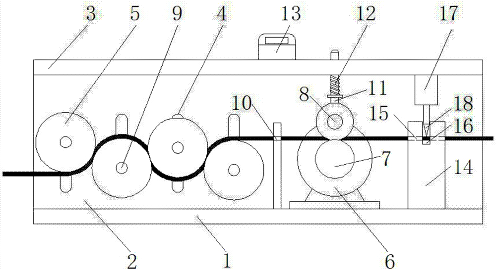
[0017] Such as figure 1 As shown, a cable pulling and cutting device includes a fixed bracket, a pulling assembly and a cutting assembly, the pulling assembly and the cutting assembly are installed on the fixing bracket, the fixing bracket includes a horizontally arranged bottom plate 1, a vertically arranged side plate 2 and The bottom plate 1 is parallel to the top plate 3, and the side plate 2 is longitudinally provided with an adjustment hole array composed of oblong adjustment holes 4. There are at least three adjustment holes 4, preferably four adjustment holes 4 in this embodiment.

[0018] The traction assembly includes a tension adjustment wheel 5, a speed regulating moto...


PUM


Abstract

The invention discloses a cable pulling and cutting device comprising a fixed support, a pulling assembly and a cutting assembly. The pulling assembly and the cutting assembly are both installed on the fixed support. A regulation hole array formed by long circular regulation holes are longitudinally formed in a side plate of the fixed support. Supporting shafts installed in the regulation holes are sleeved with tension regulation wheels in the pulling assembly. A speed regulation motor is fixed to a bottom plate. A pulling wheel is arranged on an output shaft of the speed regulation motor. A rotating wheel is arranged above the circle center of the pulling wheel. A supporting rod is arranged on a top plate. The bottom end of the supporting rod is connected with a center shaft of the rotating wheel. A cutting base in the cutting assembly is fixed to the bottom plate. A cylinder is installed on the portion, over the cutting base, on the top plate. A cutting knife is connected with a pushrod of the cylinder and faces the cutting base. Damage to cables is reduced through cooperation of the tension regulation wheels. The cables can be more rapidly and safely pulled through cooperationof the rotating wheel and the pulling wheel. The cylinder drives the cutting knife to cut the cables, and cable cutting can be more accurate and efficient.

Description

technical field [0001] The invention relates to the field of cable processing, in particular to a cable pulling and cutting device. Background technique [0002] Cable is a general term for items such as optical cables and cables. There are many uses of cables, mainly used for multiple functions such as control installation, connection equipment, power transmission, etc. It is a common and indispensable thing in daily life. In the process of cable processing and production, cable traction is indispensable. It is a missing step, but in the process, there are many problems that need to be solved urgently. During the pulling process of the cable, it takes a lot of manpower and material resources, and it is often damaged due to excessive tension between the cables, which will damage the quality of any part or process part of the cable. For this cable, it is almost It is irreparable and irreparable, and the subsequent treatment is very negative, either sawing short or downgradi...

Claims


Application Information

Patent Timeline
Patent Type & Authority Applications(China)
IPC IPC(8): B21F11/00B21F23/00B21C51/00
CPCB21F11/00B21C51/00B21F23/00
Inventor 顾华许波孙梁
Owner 苏州华安普新能源科技有限公司
Why Eureka
Try Eureka