Automatic cable shearing and bundling device

A strapping device and automatic technology, applied in the parts, packaging, transportation and packaging of strapping machinery, can solve the problems of low cable cutting and bundling efficiency, low degree of automation, and easy cable damage, and achieve high cutting and bundling efficiency. , high degree of automation, fast and safe effect of cable pulling process

Inactive Publication Date: 2016-12-14
GANZHOU JINXINNUO CABLE TECH
View PDF9 Cites 7 Cited by
  • Summary
  • Abstract
  • Description
  • Claims
  • Application Information

AI Technical Summary

Problems solved by technology

[0006] In order to overcome the disadvantages of low automation, time-consuming and labor-intensive cable cutting and binding process under the existing technical conditions, resulting in low efficiency of cable cutting and binding, easy damage of cables and high processing cost, the technical problem to be solved by the present invention is Provide an automatic cable cutting and binding device with high degree of automation, high cutting and binding efficiency, and not easy to damage the cables

Method used


Image

  • Automatic cable shearing and bundling device
  • Automatic cable shearing and bundling device
  • Automatic cable shearing and bundling device

Examples


Embodiment 1

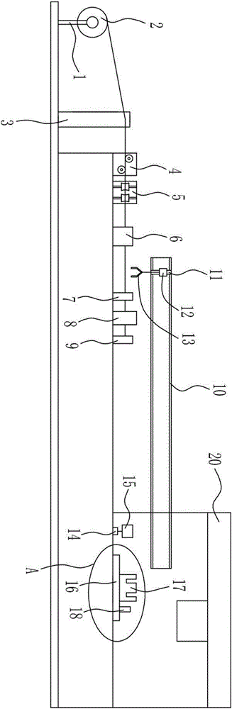
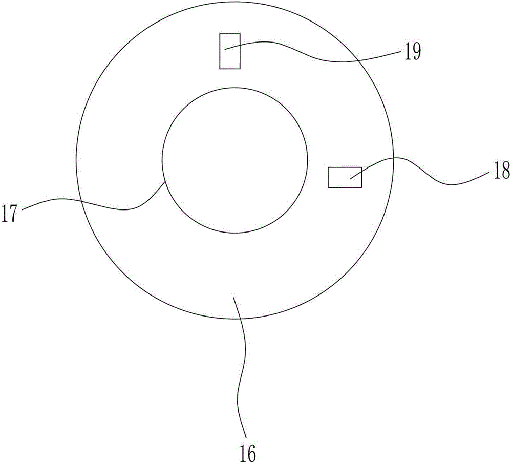
[0026] A cable automatic cutting and binding device, such as Figure 1-Figure 2 As shown, it includes pay-off frame 1, tension control device 3, horizontal guide wheel 4, vertical guide wheel 5, wire guard 6, thread clamp I7, pneumatic cutter 8, thread clamp II9, horizontal guide rail I10, Vertical guide rail 11, guide block 12, manipulator I13, cylinder I14, thread gripper III15, pneumatic turntable 16, winding frame 17, thread gripper IV18, thread gripper V19 and wire binding device 20; the right side of pay-off frame 1 A tension control device 3 is provided, the right side of the tension control device 3 is provided with a horizontal guide wheel 4, the right side of the horizontal guide wheel 4 is provided with a vertical guide wheel 5, the right side of the vertical guide wheel 5 is provided with a wire guard 6, and the wire guard The right side of sleeve 6 is provided with thread gripper I7, the right side of thread gripper I7 is arranged with thread gripper II9, the pneu...

Embodiment 2

[0028] A cable automatic cutting and binding device, such as Figure 1-Figure 6 As shown, it includes pay-off frame 1, tension control device 3, horizontal guide wheel 4, vertical guide wheel 5, wire guard 6, thread clamp I7, pneumatic cutter 8, thread clamp II9, horizontal guide rail I10, Vertical guide rail 11, guide block 12, manipulator I13, cylinder I14, thread gripper III15, pneumatic turntable 16, winding frame 17, thread gripper IV18, thread gripper V19 and wire binding device 20; the right side of pay-off frame 1 A tension control device 3 is provided, the right side of the tension control device 3 is provided with a horizontal guide wheel 4, the right side of the horizontal guide wheel 4 is provided with a vertical guide wheel 5, the right side of the vertical guide wheel 5 is provided with a wire guard 6, and the wire guard The right side of sleeve 6 is provided with thread gripper I7, the right side of thread gripper I7 is arranged with thread gripper II9, the pneu...


PUM


Abstract

The invention relates to a shearing and bundling device, in particular to an automatic cable shearing and bundling device which is high in automation degree, high in shearing and bundling efficiency, and not prone to cause damage to a cable. The automatic cable shearing and bundling device comprises a paying-off frame, a tension control device, a horizontal guide wheel, a vertical guide wheel, a bushing, a cable clamp I, and the like. The tension control device is arranged on the right side of the paying-off frame. The horizontal guide wheel is arranged on the right side of the tension control device. The vertical guide wheel is arranged on the right side of the horizontal guide wheel. The bushing is arranged on the right side of the vertical guide wheel. The cable clamp I is arranged on the right side of the bushing. The automatic cable shearing and bundling device overcomes the defects that under the prior art conditions, in the cable shearing and bundling process, the automation degree is low, time and labor are consumed, the cable shearing and bundling efficiency is low, a cable is prone to damage, and the machining cost is high, and achieves the effects that the automation degree is high, the shearing and bundling efficiency is high, and the cable is not prone to damage.

Description

technical field [0001] The invention relates to a cutting and binding device, in particular to an automatic cable cutting and binding device. Background technique [0002] With the development of science and technology, cables occupy an increasingly important position in production and life. Cables have many uses, mainly for multiple functions such as control installation, connection equipment, and power transmission. Cables are used in all aspects of production and life, and in the process of cable processing and production, cable cutting and bundling are indispensable steps, but in this process, there are many problems that need to be solved urgently. [0003] Cable pulling is unavoidable when cutting and bundling cables. During the cable pulling process, a lot of manpower and material resources are required, and irreparable damage is often caused due to excessive tension between cables. The aftermath treatment is very negative. Either sawing short or downgrading, or scra...

Claims


Application Information

Patent Timeline
Patent Type & Authority Applications(China)
IPC IPC(8): B65B63/04B65B27/06B65B13/28B65B61/06B65H59/40
CPCB65B63/04B65B13/28B65B27/06B65B61/06B65H59/40
Inventor 桂宏兵梅春风汪传灯
Owner GANZHOU JINXINNUO CABLE TECH
Why Eureka
Try Eureka